
Stepper Motor Generator

A stepper motor operates by converting electrical energy into mechanical motion through a series of discrete steps. This characteristic can be leveraged in reverse, allowing the motor to act as a generator when subjected to mechanical rotation. When the rotor of a stepper motor is turned, it induces a voltage across its windings due to electromagnetic induction, which is the principle behind generator operation.
The induced voltage is a function of the speed of rotation and the design of the motor. At low rotational speeds, stepper motors can produce a surprisingly high voltage, making them suitable for applications where low-speed mechanical energy needs to be converted into electrical energy, such as in renewable energy systems or energy harvesting devices.
The output voltage can be monitored and regulated, and additional circuitry may be required to condition the generated voltage for specific applications. This includes rectification, filtering, and voltage regulation to ensure that the output meets the required specifications for the load being powered.
In practical applications, the use of a stepper motor as a generator can be integrated into systems where mechanical energy is available, such as wind turbines or human-powered devices, enhancing energy efficiency and sustainability. Proper selection of the stepper motor based on its specifications, including winding configuration and step angle, is crucial to optimize performance when used in generator mode.Any stepper motor can be used as a generator. In contrast to other generators, a stepper motor produces a large induced voltage even at low rotational spe.. 🔗 External reference
Related Circuits
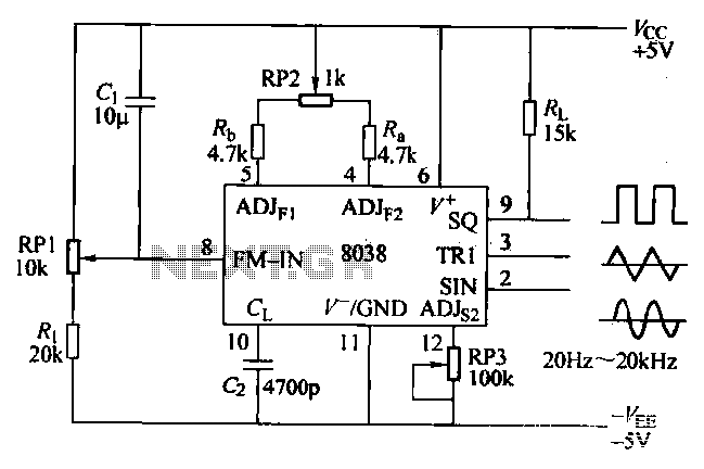
The ICL8038 function generator is an audio composition device that utilizes the ICL8038 integrated circuit. The resistance Ri potentiometer RP1 is used to determine the flow potential. Typically, the output is set to approximately 2Vcc / 3. Lowering the...
The output level was set to 3.8V peak to peak. The initial objective was to compare several different operational amplifiers (op-amps) before further optimizing the circuit. The op-amps evaluated were the TL072, LM4562, and OPA2134. The distortion spectra are...
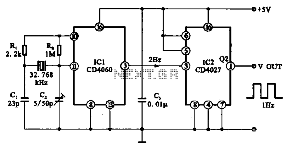
A 1Hz clock signal generator circuit is presented, which demonstrates a sophisticated clock signal generating mechanism. This circuit can be utilized for digital clocks and timing applications. It comprises a binary counter (CD4060), a JK flip-flop (CD4027), and a...
Here is an updated schematic featuring the RF Solutions receiver along with several minor additions. The design includes additional circuitry to manage the signals effectively. The updated schematic incorporates an RF Solutions receiver, which is essential for receiving radio frequency...
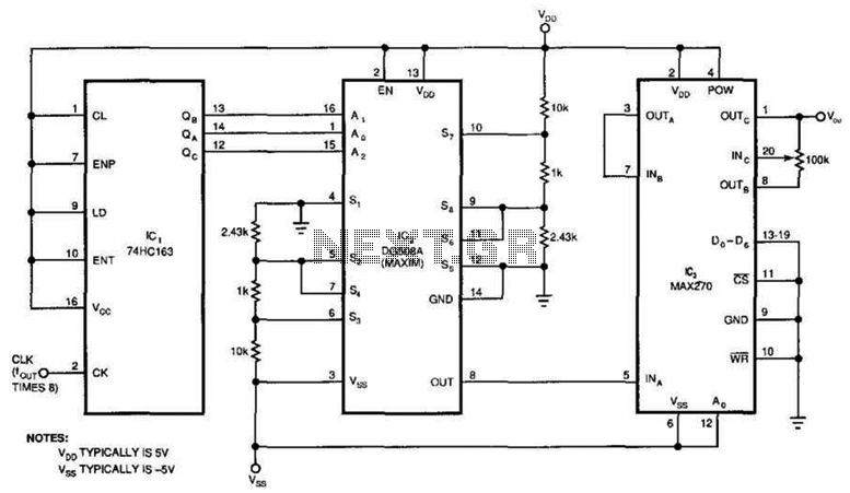
This circuit generates a pure sine wave with a total harmonic distortion (THD) of -80 dB and a frequency equal to the cutoff frequency (fc) of the filter in IC3. It utilizes a counter, an 8-channel analog multiplexer, and...
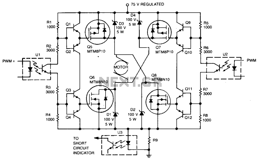
Digital integrated circuits (ICs) and opto-isolators drive this TMOS servo amplifier, resulting in fewer analog circuits and reduced drift. The fast and consistent turn-on and turn-off characteristics enable accurate analog output results directly from the digital signal without requiring...