
Pure Sine-Wave Generator

The circuit's architecture is designed to ensure high fidelity in sine wave generation while minimizing distortion. The Sallen-Key topology is particularly effective for implementing the fourth-order low-pass filter, which is critical for attenuating unwanted harmonics and ensuring signal purity. The use of an 8-channel analog multiplexer allows for flexible signal routing, enabling the selection of various input signals based on the configured digital states of D0 through D6.
The choice of using resistive dividers to provide bipolar DC inputs is significant as it allows the multiplexer to handle a range of input levels, which is crucial for applications that require precise control over the output signal. The adjustable output level via the 100-kHz potentiometer provides additional versatility, accommodating different system requirements without the need for additional components.
The requirement for the clock frequency to be eight times the cutoff frequency is a critical design consideration, as it ensures that the output signal is adequately oversampled. This oversampling technique is advantageous because it reduces the complexity of the filtering process, allowing for a more straightforward implementation of the low-pass filter while maintaining the integrity of the desired sine wave output.
Overall, this circuit exemplifies a well-engineered solution for generating high-quality sine waves with minimal distortion, suitable for various applications in signal processing and waveform generation. This circuit produces a pure, - 80-dB THD sine wave with a frequency that is equal to the fc of IC3"s filter. A TT L counter, an 8-channel analog multiplexer, and a fourth-order low-pass filter can generate 1- to 25-kHz sine waves with a THD of better than - 80 dB. The circuit cascades the two second-order, continuous-time Sallen-Key filters within IC3 to implement the fourth-order low-pass filter.
Two resistive dividers connected from ground to VDD and ground to Vss provide bipolar dc inputs to the multiplexer. lb operate the circuit, you first must choose the filter"s cutoff frequency, fc, by tying IC3"s D0 through D6 inputs to 5 V or ground.
The cutoff frequency can be at 128 possible levels between 1 and 25 kHz, depending on those 7 digital input levels. Because this figure ties Z)0 through D6 to ground, fc equals 1 kHz. The 100-kHz potentiometer adjusts the output level anywhere from 1.5 V below Vdd to 1.5 V above Vss-The clock input frequency must be 8 times higher than the filter"s fc.
The multiplexer then produces an 8x oversampled staircase approximation of a sine wave. 8 oversampling greatly simplifies the smoothing requirements of the low-pass filter by pushing the first significant harmonic out to 7 the fundamental. All higher-order harmonics are removed by IC3, which includes an uncommitted amplifier for setting the output level.
🔗 External reference
Related Circuits

With a dual supply voltage, the external capacitor on pin 10 can be connected to ground to stop the oscillation of the 8038. The circuit employs a FET switch and a diode, which are combined with an input strobe...
This signal generator is designed for the realignment of radio receivers. The unit is inexpensive and relatively simple but adequately serves its intended purpose. However, the output is not a pure sine wave, which may make it unsuitable for...
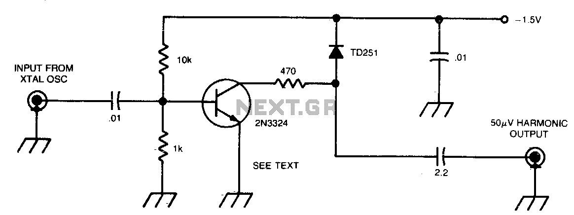
This circuit generates 50 µV harmonics at frequencies up to 1296 MHz, utilizing an input voltage of 0.5 to 1 V from a 100 or 1000 kHz crystal oscillator. By employing a germanium diode instead of a tunnel diode,...
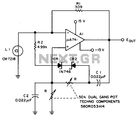
The Lamp LI stabilizes the loop gain at higher frequencies, while the limiting action of R2, CRI, and CR2 prevents clipping at low frequencies and increases the frequency adjustment range from approximately 3:1 to over 10:1. Additionally, waveform purity...
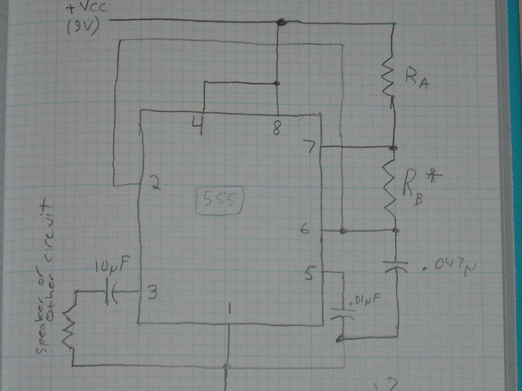
This is a basic 555 square wave oscillator designed to generate a 1 kHz tone for an 8-ohm speaker. In the circuit, the speaker is isolated from the oscillator by an NPN medium power transistor, which supplies more current...
A new project has been selected for the upcoming year, which is an improvement over the previous project, a homemade x-ray machine. The chosen project involves developing a safer and more efficient electronic device, replacing the homemade x-ray machine that...