
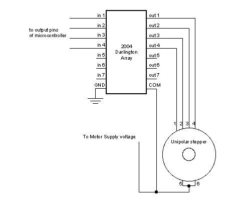
Stepper Motor Interface to Microcontroller

The described circuit utilizes an H-Bridge configuration to drive a bipolar stepper motor, allowing for precise control of the motor's motion and direction. The H-Bridge consists of four switches (typically MOSFETs or transistors) arranged in a bridge layout, enabling the application of voltage across the motor coils in both directions. This arrangement is essential for reversing the motor's direction, which is achieved by activating the appropriate controller pins in a specific sequence.
The controller pins are connected to the input terminals of the H-Bridge. When a high signal is sent to "Controller pin 1," it activates one side of the H-Bridge, allowing current to flow through one coil of the motor. Activating "Controller pin 2" simultaneously allows current to flow through the opposite coil, creating a magnetic field that causes the motor to step. The sequence of activating these pins determines the stepping pattern, which can be full-step, half-step, or micro-stepping, depending on the desired resolution and smoothness of the motor's operation.
The programming of the microcontroller involves defining the step sequence and timing for each pin activation. This can be achieved using a timer interrupt or a loop that iterates through the defined sequence, ensuring that the timing between steps is consistent with the motor's specifications. Proper timing is critical to prevent missed steps or stalling, particularly under load.
In summary, the circuit's design and the programming of the microcontroller work in tandem to achieve precise control of the bipolar stepper motor's motion. The implementation of an H-Bridge allows for versatile control of the motor's direction and speed, making it suitable for various applications in robotics, automation, and precise positioning systems.As you see in the circuit above the four pins "Controller pin 1", 2, 3 and 4 will control the motion and direction of the stepper motor according to the step sequece programmed in the controller. As already discussed in case of L293D, Here in this circuit too the four pins "Controller pin 1", 2, 3 and 4 will control the motion and direction of the ste
pper motor according to the step sequece sent by the controller. As we have studied that, Bi-polar stepper motors has 2 different coils. The step sequence for Bipolar stepper motor is same as that of unipolar stepper motors. The driving circuit for this require an H-Bridge as it allows the polarity of the power applied to be controlled independently. This can be done as shown in the figure below: Now we have seen the methods for connecting stepper motors with your microcontroller.
So keeping these circuits in mind, we will now look at the programming of microcontroller to control stepper motors. 🔗 External reference
Related Circuits
The challenge is to control the speed of the motor. One approach is to use a plane, radio, and speed control integrated with the motor, but this is not ideal. Alternatively, mounting the motor on a bench and directly...
Stepper motors, because of their distinct design, can be operated with a high level of precision without the need for feedback mechanisms. The shaft of a stepper motor, equipped with a series of magnets, is governed by a set...
Building circuits to interface an Amiga A1200 to a PC AT/ATX power supply and tower case. To create a reliable interface between an Amiga A1200 and a PC AT/ATX power supply and tower case, it is essential to design a...
This design note presents a simple yet feature-rich 16-watt output, universal AC input adapter power supply for modems, hubs, or similar applications. The circuit utilizes a discontinuous mode (DCM) flyback converter topology designed around ON Semiconductor's NCP1027 monolithic current...
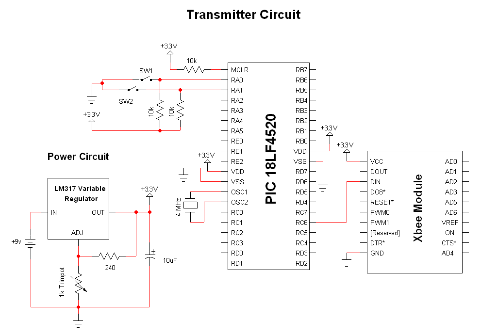
The advantage of these compact Xbee modules is that they handle most of the complex tasks. The transmitter and receiver circuits are both straightforward. The primary components in the circuit include the Xbee Modules, PIC 18LF452, and LM317. Both...

The microcontroller design features the microcontroller (MCU) in hibernation mode, which can only be awakened by a pulse (high-low-high) signal on the reset pin (active low). An accelerometer or an external real-time clock (RTC) serves as the wake-up source....