
Xbee Wireless Interface Circuit

The Xbee modules serve as the primary communication interface, enabling wireless data transmission between the transmitter and receiver circuits. The PIC 18LF452 microcontroller, known for its versatility, is used in both circuits to manage operations and data processing. The LM317 voltage regulator ensures that both circuits operate within the specified voltage range, providing a stable +3.3V output necessary for reliable performance. The choice of a 10µF capacitor for noise filtering is critical, as it helps mitigate voltage fluctuations and maintains a stable power supply to the microcontroller and Xbee modules.
In the transmitter circuit, the integration of two buttons allows for user input, which is essential for initiating data transmission. The use of a pull-up resistor ensures that the microcontroller can accurately detect button presses, translating them into digital signals that can be wirelessly transmitted. The connection of PortB pin 0 to the Xbee Din pin is crucial for sending data to the receiver, highlighting the importance of proper pin assignments in microcontroller interfacing.
Conversely, the receiver circuit is designed to output received data through an LED, providing a visual indication of successful data reception. The connection of PortB pin 0 to the Xbee Dout pin allows the microcontroller to read the incoming data stream, which can then be processed or displayed as needed. This setup exemplifies a simple yet effective wireless communication system, leveraging the capabilities of the Xbee modules and the PIC microcontroller to facilitate seamless data exchange in various applications.The great thing about these little Xbee modules is they take care of almost all the heavy lifting. As you can see below both the transmitter and the receiver circuits are drop-dead simple. The main devices used in the circuit are the Xbee Modules, PIC 18LF452 and LM317. Both circuits use the same simple power regulation circuit with the LM317 f or +3. 3v reg. An output capacitor of 10uF is used for noise filtering which helps keeps the output DC signal stable around +3. 3v. A 1k or 5k trimmer is used with a 240ohm resistor to create the adjustable voltage to the required +3.
3v The transmitter circuit has the standard PIC 18LF4520 power, ground, MCLR and crystal connections. In addition to the normal connections, two buttons are connected to PORTA pins 0 and 1. A pull up resistor of 10k © is used so that the digital input seen is +5v or logic 1. When either button is pressed, the input is connected to ground/+0v making the input a logic 0. PortB pin 0 is connected to the Xbee Din pin. This is for the wireless data to be output to the receiver. The receiver circuit has the same standard PIC power, ground, MCLR and crystal connections. The difference between the transmitter is instead of input via buttons, we are showing output with an LED.
Similarly, the PORTB pin 0 is connected to the Dout pin of the Xbee module so that the wirelessly transmitted information can be received. 🔗 External reference
Related Circuits
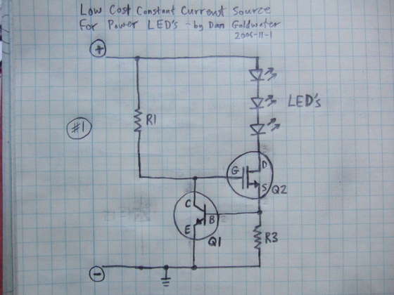
Here is a simple and cost-effective Power LED driver circuit. This power LED driver circuit is designed to efficiently drive high-power LEDs with a stable output. The circuit typically consists of a few key components: a power supply, a current...
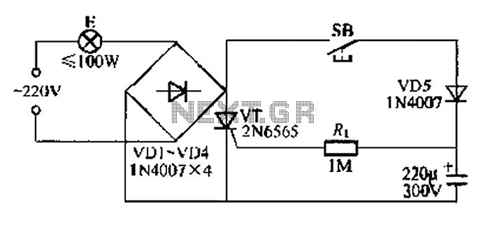
This circuit is a simple connection delay lamp circuit. When the lights are turned on and the switch is pressed, the power supply is activated. The capacitor charges rapidly, causing the thyristor (VT) to open, which in turn lights...
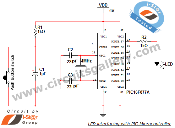
How to interface an LED with Microchip's PIC microcontroller. Connecting LEDs to a PIC microcontroller is fundamental for microcontroller development. This guide presents a simple embedded program for the PIC 16F877A to interface LEDs, making it suitable for beginners...
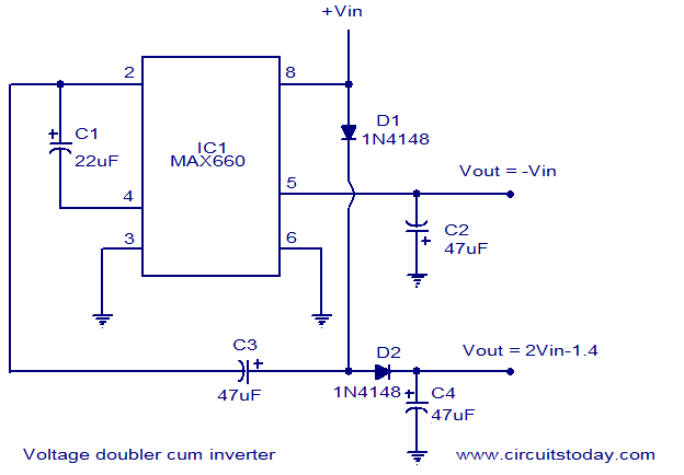
Voltage doubler circuit and voltage inverter circuit diagram with schematics using MAX660 IC, which is a DC voltage multiplier IC. This is a DC voltage doubler circuit and inverter. The MAX660 integrated circuit (IC) is designed for applications requiring a...
The following circuit illustrates a Water Level Detector Circuit Diagram. This circuit is based on the PIC12F683 microcontroller. Features include the ability of the PIC microcontroller to enter a sleep mode. The Water Level Detector Circuit utilizing the PIC12F683 microcontroller...
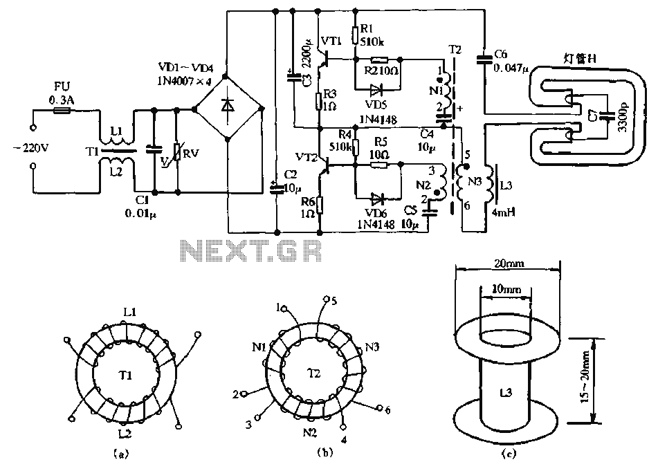
The circuit diagram illustrates a dedicated electronic ballast circuit for a 16W2D single-ended energy-saving lamp. The RFI filter circuit consists of components such as zinc oxide varistors for protection, bridge rectifiers, a high-frequency oscillator, and an LC series output...