
stepper remote control car

The stepper motor control circuit is designed to manage the operation of a stepper motor, specifically utilizing the TLE5206 integrated circuit. This circuit is particularly suitable for applications in remote control cars, where precise motor control is essential for maneuverability and performance.
The TLE5206 is a dual H-bridge driver that allows for bidirectional control of the stepper motor. It can handle a wide range of supply voltages and provides built-in protection features such as thermal shutdown and overcurrent protection, ensuring reliable operation in varying conditions.
In the schematic, the stepper motor is connected to the outputs of the TLE5206, which are configured to drive the motor phases. The control signals for the TLE5206 can be generated from a microcontroller or a dedicated control circuit, which sends step and direction commands to the driver. The microcontroller typically outputs pulse-width modulation (PWM) signals that dictate the speed and direction of the motor.
Additional components in the circuit may include capacitors for power supply decoupling, resistors for current limiting, and diodes for flyback protection, which safeguard the circuit from voltage spikes caused by the inductive load of the stepper motor. The design should also include provisions for heat dissipation, as the TLE5206 may generate heat during operation, especially under load.
Overall, this stepper motor control circuit is a robust solution for controlling the motion of stepper motors in remote control applications, providing both efficiency and reliability through the use of the TLE5206 driver.Stepper motor control circuit Stepper motor control circuit diagram using TLE5206 for remote control car.. 🔗 External reference
Related Circuits
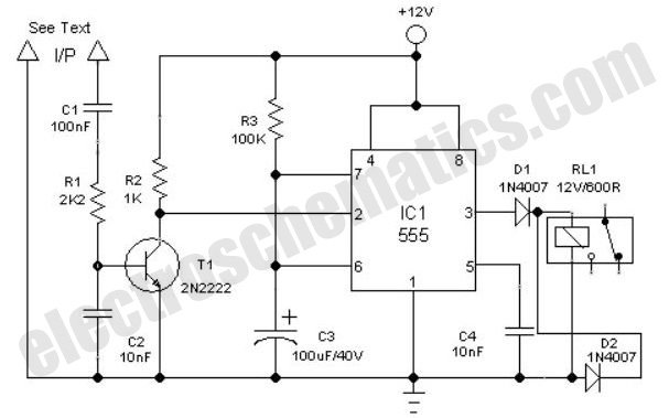
Constantly changing light and sound analog controller circuit 01 The described circuit functions as an analog controller designed to modulate light and sound outputs in a dynamic manner. This circuit typically integrates various electronic components, including resistors, capacitors, transistors, and...
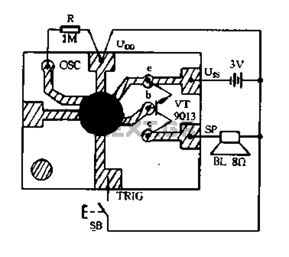
This is a simple toggle switch that can be operated through sound signals such as a whistle or clap. The output of the toggle remains either low or high until... This circuit utilizes a sound sensor to detect specific audio...
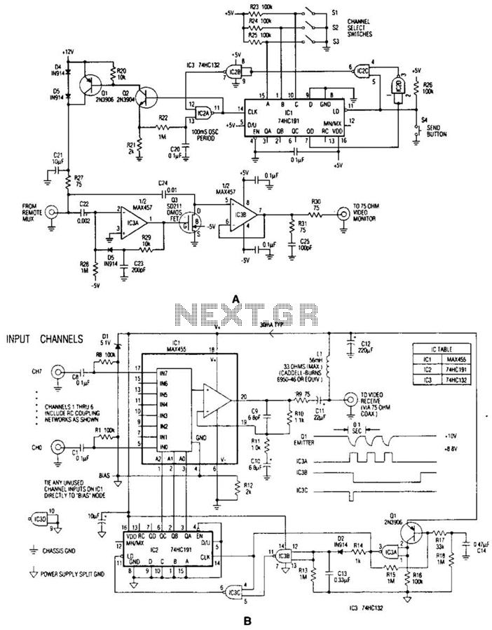
In the video system illustrated in Figures A and R, a single coaxial cable transmits power to a remote location, selects one of eight video channels, and returns the selected signal. This system can choose from several remote surveillance...
If EAGLE is not available, a full working version can be downloaded from CadSoftUSA. A zip file containing the EAGLE schematics is provided. The EAGLE software is a widely used electronic design automation (EDA) tool that facilitates the creation of...
A very simple controller circuit with impressive performance. If a fully automatic computer-controlled rotator is not affordable but enhanced capability is desired from a basic rotator, the ZL1BPU Rotator Controller offers a simple "point and shoot" computer-controlled antenna solution....
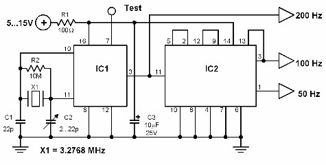
This circuit generates a 50 Hz timebase signal that is independent of the power line frequency. It is designed to provide the 50 Hz signal for electronic circuits that operate specifically with this clock frequency, primarily for circuits and...