
Video Signal Carrier Circuit

The video system described employs a coaxial cable as a multifunctional medium, enabling both power supply and video signal transmission. The multiplexer box (A) integrates an 8-channel multiplexer and an amplifier (IC1) that are essential for managing multiple video signals. The coupling capacitor (C1) is critical for ensuring that the baseband video signal is effectively transmitted over the coaxial cable without interference from the DC power. The inductor (L1) serves to isolate the video signal from the DC power line, preventing any potential disruptions that could arise from shared pathways.
Within the interface box (B), the channel selection mechanism operates through a binary encoding system, utilizing three bits to represent eight possible channels. This encoding can be accomplished through physical switches or by an external digital input, providing flexibility in operation. The momentary activation of the send button initiates a sequence that involves the downconverter IC1 and the gated oscillator IC2A. This sequence is crucial for generating a channel-selection burst, which ensures that the correct video channel is selected and displayed.
The design of this system emphasizes efficiency and reliability, particularly in environments where remote surveillance is necessary. The coaxial cable's dual function minimizes the need for additional wiring, reducing installation complexity and potential points of failure. Overall, this video system exemplifies an effective integration of signal processing and power distribution, suitable for various surveillance applications. In the video system of Figs. A and R, a single coaxial cable carries power to the remote location, selects one of eight video channels, and returns the selected signal. The system can choose one of several remote surveillance-camera signals, for example, and display the picture on a monitor near the interface box.
The heart of the multiplexer box (A) is a combination 8-channel multiplexer and amplifier (IC1). Cll couples the multiplexer`s baseband video output to the coax, and LI decouples the video from dc power arriving on the same line, This powerapproximately 30 mA at 10 Vsupplies all circuitry in the multiplexer box. In interface box (B), a desired channel is encoded by three bits, set either by switches as shown or by an applied digital input. Momentary depression of the send button triggers downconverter IC1 and gated oscillator IC2A to initiate a channel-selection burst,
Related Circuits
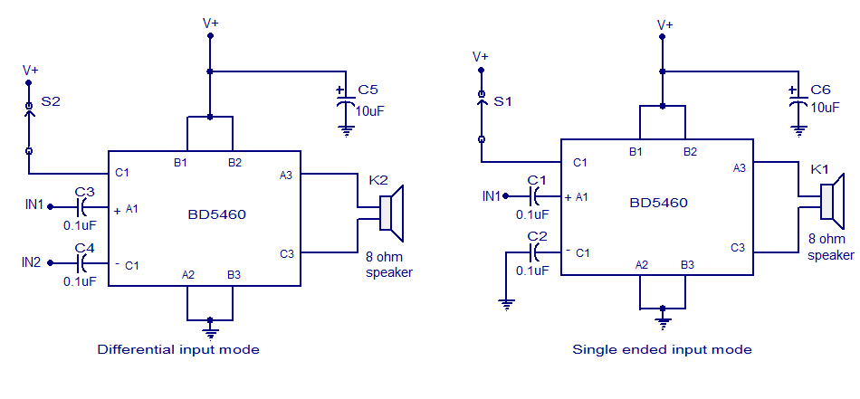
The BD5460 is a low power Class D amplifier that can be utilized in low power applications such as handheld audio devices. The BD5460 does not require an LC filter at the speaker output and can be powered by...
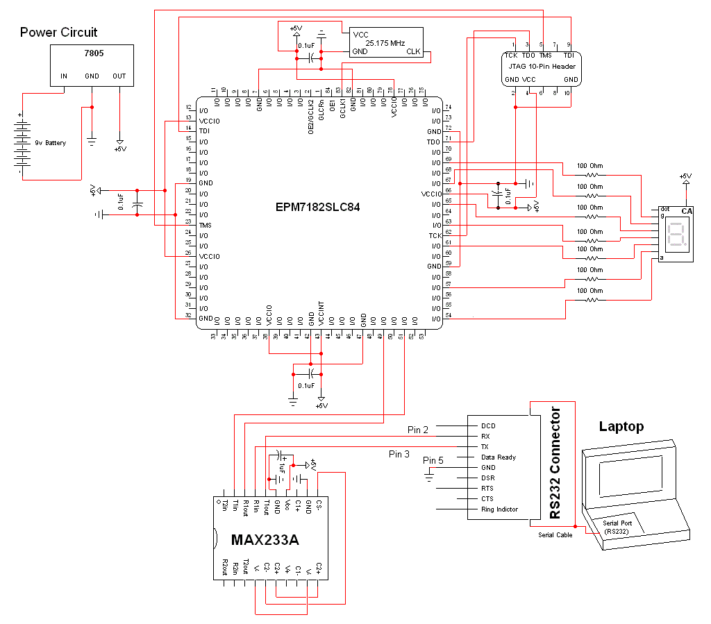
The schematic for this project is a modified version of the CPLD development board schematic. Several new components have been added for this project, and the completed schematic can be viewed below. The main components in the schematic are...
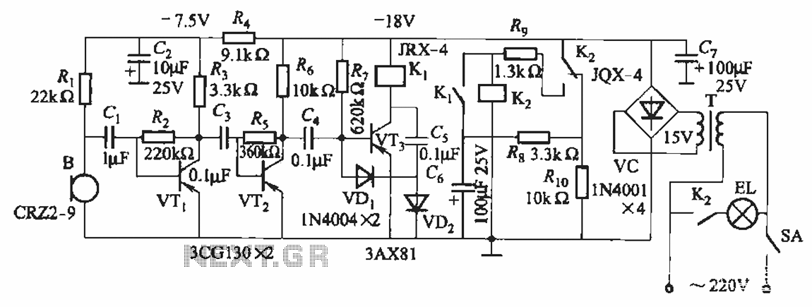
The circuit utilizes relay control. The voice switch operates as follows: upon the first clap, the load (lights) is activated; upon the second clap, the load (lights) is deactivated. This system can be employed to control lighting in residential...
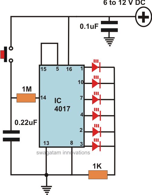
This article offers a circuit diagram and a discussion on CMOS logic and IC layout for creating a set of attention-getting LED running lights. It details a simple sequential LED flasher or light chaser that can be built, including...
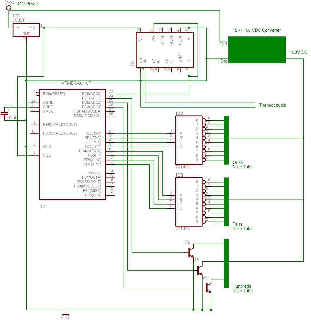
the entire circuit is comprised of integrated circuits. This makes for some easy organization when it goes to the circuit board for soldering. In addition, I used only 3 of the pins on the 3rd nixie tube for the...
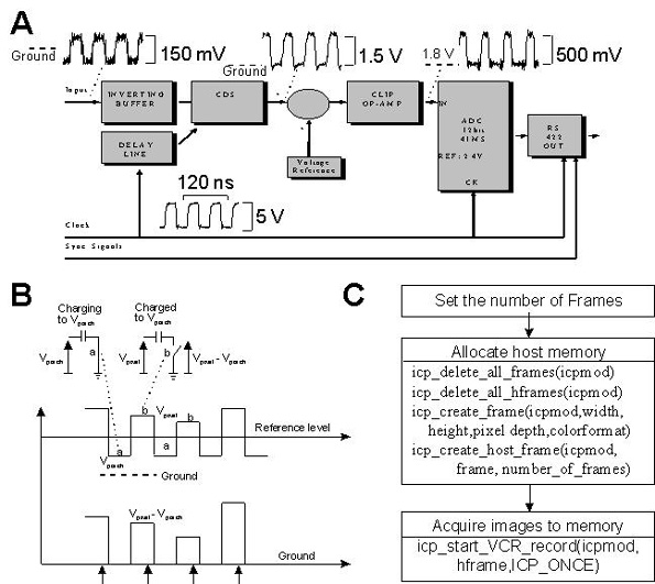
This document provides technical details regarding the hardware and software of a complete imaging system that utilizes a fast CCD sensor and a 41 Msample/s A/D converter. This system is capable of acquiring full-frame digitized images at a resolution...