
Stereo Audio Isolator

The circuit designed for removing ground loop hum typically involves the use of audio transformers or differential amplifiers to isolate the audio signal from ground potential variations. The primary function of this circuit is to eliminate unwanted noise that can occur when there are multiple ground connections between devices, which can introduce hum and interference into the audio signal.
In the context of connecting a computer sound card to a stereo amplifier, the circuit may consist of an input stage where the audio signal from the sound card is fed into a transformer. This transformer serves to provide electrical isolation, ensuring that any ground potential differences do not affect the audio signal quality. The secondary winding of the transformer outputs the isolated audio signal, which can then be connected to the line input of the amplifier.
For applications involving remote amplifiers, the circuit can be equipped with additional features such as level adjustment controls, allowing for optimal signal strength before amplification. Furthermore, the circuit can be designed to operate at 12 volts, making it suitable for automotive audio systems where common mode ground interference is prevalent. In such cases, capacitors and resistors can be strategically placed to filter out high-frequency noise while maintaining the integrity of the audio signal.
In mono applications, the circuit can be simplified by using only one channel of the transformer, effectively ignoring the second channel. This approach ensures that the design remains compact and cost-effective while still achieving the desired noise reduction.
Overall, this circuit serves as an essential tool for audio professionals and enthusiasts seeking to maintain high-quality audio signals in various applications while minimizing the impact of ground loop hum and interference.This circuit is useful for removing ground loop hum on a remote line level audio signal line. It can be used to to connect a computer sound card to a stereo amplifier`s line input. Other uses include tapping into a line level signal for powering a remote amplifier, and removing common mode ground interference on 12 Volt audio equipment such as a car stereo. The circuit can be used in mono applications by simply ignoring the second channel. 🔗 External reference
Related Circuits
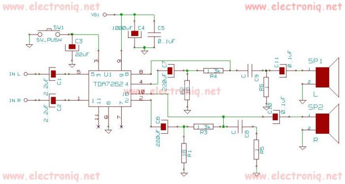
TDA7262 stereo 20 watts audio amplifier circuit design electronic project The TDA7262 is an integrated circuit designed for stereo audio amplification, capable of delivering up to 20 watts per channel. This amplifier circuit is suitable for various applications, including home...
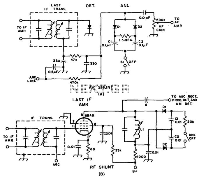
Examples of RF and audio ANL circuits. Positive and negative clipping occurs in both circuits. The circuit is self-adjusting. This noise limiter operates at the IF output. Adequate gain is needed at the IF frequency so that several volts...
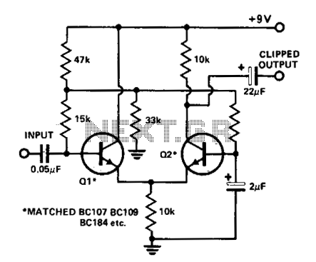
A differential amplifier serves as an effective audio clipper, capable of delivering precise and symmetrical clipping. The circuit presented begins clipping at an input voltage of 100 mV, with the output starting to clip at ±3 V. For optimal...
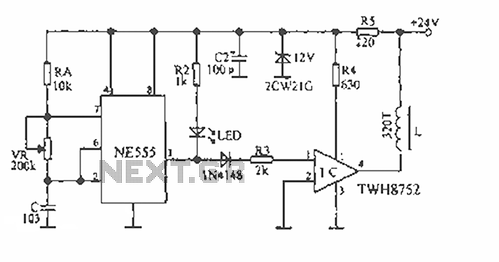
The device is designed to accelerate the defrosting process of fish, meat, and other foods by utilizing audio vibrations. This method allows for defrosting in warm water, significantly reducing the time required compared to conventional methods, while preserving the...
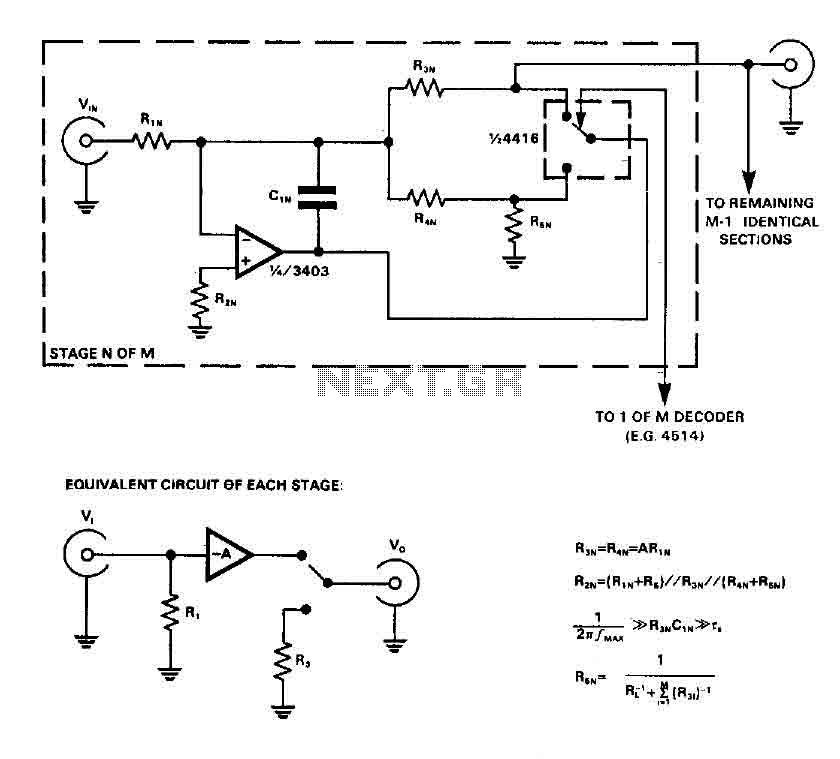
CMOS switches are utilized to select entries in audio circuits. While these switches can introduce unacceptable levels of distortion, incorporating them into the feedback network of an operational amplifier (op amp) can effectively minimize this distortion. The circuit employs...

This design circuit for audio amplifiers with DC coupling to the load is not commonly used today, despite its clear advantages. One advantage is the elimination of the need for a second (symmetric) power supply, and another is the...