
Audio Shunt Noise Limiter

The RF (Radio Frequency) and audio ANL (Automatic Noise Limiter) circuits serve critical functions in signal processing, particularly in minimizing unwanted noise while maintaining signal integrity. These circuits are designed to handle both positive and negative clipping, ensuring that signal distortions are effectively managed.
The self-adjusting feature of the circuit allows it to adapt to varying input signal levels, which is particularly beneficial in environments with fluctuating noise levels. This adaptability is crucial for maintaining audio quality, as it ensures that the limiter can respond dynamically to changes in the incoming signal.
Operating at the Intermediate Frequency (IF) output, the noise limiter plays a vital role in enhancing the performance of RF systems. It is essential for the circuit to achieve adequate gain at the IF frequency. This gain is necessary to ensure that the output audio signal can reach several volts peak-to-peak, providing sufficient amplitude for further processing or amplification stages.
In practical applications, these circuits can be integrated into various devices, including radios, audio processors, and communication systems, where they contribute to clearer sound reproduction and improved overall performance by effectively managing noise and signal clipping. Proper design considerations must be taken into account to optimize the gain and ensure the self-adjusting mechanism functions as intended, thereby achieving the desired audio quality and reliability in the output signal. Examples of RF and audio ANL circuits. Positive and negative clipping occurs in both circuits. The circuit at A i s self-adjusting. This noise limiter operates at the IF output. It is self-adjusting. Adequate gain is needed at the IF frequency so that several volts p-p of audio is available.
Related Circuits
Measures 10mV to 50Volt RMS in eight ranges. Simply connect to your Avo-meter set to 50µA range. Connect J2 and J3 to an Avo-meter set to 50µA range. Switching SW2 the four input ranges will be multiplied by 5....
The objective of this project was to design a small, portable mixer powered by a 9V PP3 battery while maintaining high-quality performance. The mixer consists of three main modules that can be varied in number and/or arrangement to meet...
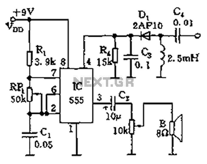
The circuit features a 555 timer integrated circuit along with components R1, RP1, C1, and others, which together form an audio oscillator. The frequency of the oscillator is determined by the formula f = 1.44 / ((R1 + 2...
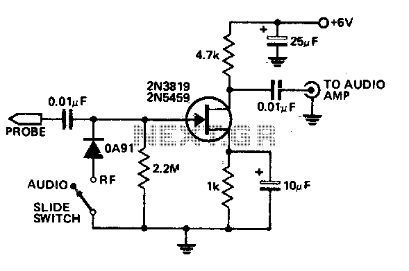
This economical signal tracer is useful for servicing and alignment work in receivers and low power transmitters. When switched to RF, the modulation on any signal is detected by the diode and amplified by the FET. A twin-core shielded...
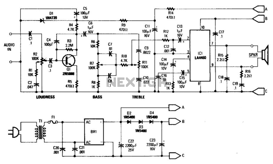
This general-purpose low-power (5 W) audio amplifier is designed to drive speakers ranging from 8 to 12 inches. It utilizes a Sanyo LA4460 integrated circuit (IC) as the audio output component. The circuit features a loudness control, a driver...
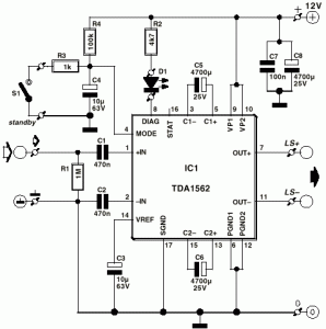
A car audio amplifier utilizing the TDA1562Q, capable of delivering 50W of audio power. The circuit diagram includes two resistors of 1 kOhm and two resistors of 4.7 kOhm. The TDA1562Q is a high-performance integrated circuit designed for car audio...