
stereo balance indicator

The stereo balance indicator circuit is a practical application for audio systems, enabling users to visually assess the balance between left and right audio channels. The circuit employs a differential amplifier configuration using an operational amplifier (IC1) to process the audio signals from both channels. The differential amplifier effectively amplifies the difference between the two input signals, allowing for precise detection of any imbalance.
The outputs of the differential amplifier (IC1) are routed to the non-inverting inputs of two additional operational amplifiers (IC2 and IC3). These amplifiers serve as comparators, determining the status of the audio balance. When the output from IC1 approaches the positive supply voltage, it indicates that the right channel is significantly stronger than the left, triggering IC2 and IC3 to output high signals. This condition activates LED3, providing a clear visual cue to the user.
Conversely, if the audio balance shifts toward the left channel, the outputs from IC2 and IC3 will drop to low levels, resulting in the illumination of LED1. This visual indication alerts the user to the dominance of the left channel. In a perfectly balanced scenario, where both audio channels are equal in amplitude, IC2 and IC3 will output a low signal for one and a high signal for the other, activating LED2. This setup allows for an intuitive understanding of the audio balance, essential for optimizing sound quality in various listening environments.
The circuit's simplicity and reliance on commonly available components make it an accessible project for audio enthusiasts and engineers alike. By implementing this stereo balance indicator in an audio system, users can ensure a more enjoyable listening experience through effective sound balance management.This stereo balance indicator circuit diagram is designed using few common external components. The schematic circuit is very simple to build and will provide an visual indication with LEDs for left, right and center balance. Outputs from each channel are fed to the two inputs of IC1 connected as a differential amplifier. Output of the IC1 is c onnected to the noninverting inputs of the IC2 and IC3. If the outputs of the IC1 approaches the supply rail, the outputs of the IC2 and IC3 will go high illuminating the LED 3, this will show that the right channel is dominating. If the sound is balanced to the left channel, the Ic2 and IC3 will go low and the LED1 will light. If both channels are equal in amplitude the outputs of the IC2 and IC3 would be low and high respectively, lighting up LED2.
🔗 External reference
Related Circuits

This design circuit is for a stereo amplifier intended for a high-sensitivity stereo parabolic microphone, enabling the listening of distant sounds. Unlike typical parabolic microphones that are monophonic, this unit features a stereo audio path, resulting in more realistic...
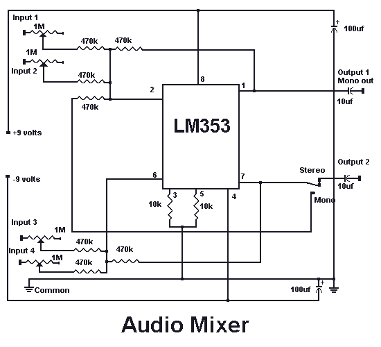
With this circuit you can mix four separate audio inputs. Each input will accept high or low impedance microphones, phonograph, tape or aux signals. You can adjust the gain of each input by adjusting each respective pot. With the...
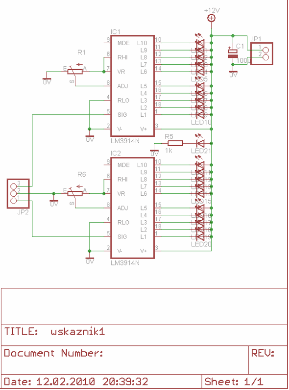
The LM3914 is a monolithic integrated circuit designed to sense analog voltage levels and drive a 20 LED stereo VU meter. It features a circuit diagram for a PCB layout using Eagle software, specifically for a 10 LED stereo...
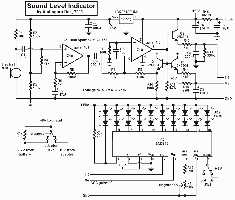
This project uses an LM3915 bar-graph IC driving two sets of ten LEDs for a 30dB range. The circuit is unique because it has an additional range of 20dB provided by an automatic gain control to allow it to...
The layout of the PC board led to the decision to insert a stereo 3mm canceling type jack (5 pin) at the volume control chip inputs, which was mounted on the front panel. A suitable jack was not available...
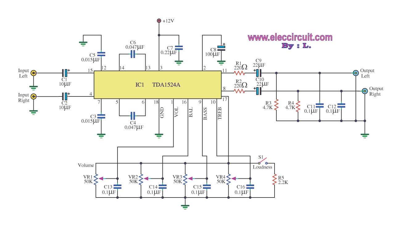
The stereo tone control circuit utilizes the integrated circuit TDA1524A. This IC serves as the central component in the design. The TDA1524A is a versatile integrated circuit designed for audio applications, particularly in tone control systems. It features a dual-channel...