
Stereo tone control circuit using IC TDA1524A

The TDA1524A is a versatile integrated circuit designed for audio applications, particularly in tone control systems. It features a dual-channel operation, allowing for independent adjustment of bass and treble levels for left and right audio channels. The circuit typically includes a power supply section that provides the necessary voltage and current to the IC, ensuring stable performance.
In a standard configuration, the TDA1524A is connected to passive components such as resistors and capacitors that define the frequency response for the tone control. The circuit often includes a potentiometer for each channel, enabling users to adjust the bass and treble settings. The output of the TDA1524A is connected to the power amplifier stage, which drives the speakers.
The schematic diagram would illustrate the connections between the TDA1524A, the tone control components, and the power supply. It is essential to follow the manufacturer's guidelines for component values to achieve the desired audio performance. Additionally, bypass capacitors may be included near the power supply pins to filter out noise and ensure stable operation.
Overall, the stereo tone control circuit with the TDA1524A provides an effective solution for enhancing audio quality by allowing users to tailor the sound to their preferences.The stereo tone control circuit with IC, be the circuit diagram that use just IC number TDA1524A. It be pillar heart in the work which, be IC the integrated.. 🔗 External reference
Related Circuits
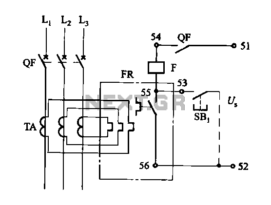
The DK-5A, 5D, and SDb control boxes are equipped with a thermal electromagnetic overcurrent release, as depicted in Figure 6-80. The trip mechanism provides both overload and instantaneous short circuit protection with a long delay feature. In the figure,...
The AquaCont is an electronic system which permits to manage and to monitor most of the parameters of all the electric devices that can be found in an aquarium. The PIC18F4520 used to realize it combines a real-time clock...
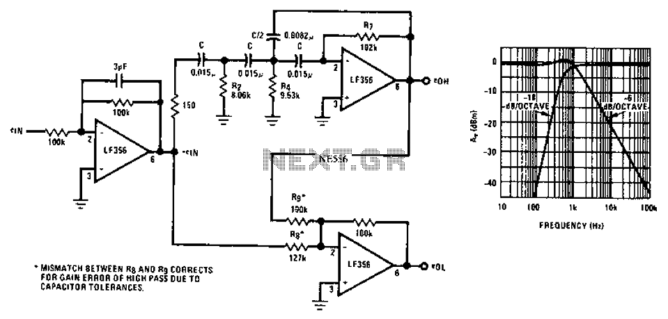
Asymmetric third-order Butterworth active crossover network circuit diagram. The asymmetric third-order Butterworth active crossover network is a sophisticated circuit designed to split an audio signal into two separate frequency bands, typically for use in multi-way speaker systems. This type of...

The circuit illustrated briefly flashes an LED to attract attention and remains illuminated as long as power is supplied. The circuit utilizes the well-known 555 timer integrated circuit (IC) configured as a standard astable multivibrator with resistors RA, RB,...
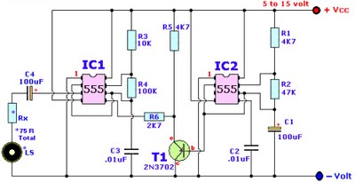
Browse home alarm circuit explanation latest schematic siren wailing with latest Wailing Alarm Siren circuit schematic with explanation. The loudspeaker LS and the resistor marked Rx should be together 75 ohms. If a standard 8-ohm speaker is used, then...
This circuit emits an intermittent beep or flashes an LED when the water level in a container reaches a predetermined height. It is designed to be mounted on top of the container, such as a plastic tank, using two...