
Stereo balance indicator

The stereo balance indicator circuit utilizes the uA741 op-amp to achieve its functionality. The op-amp is configured in a differential mode, where the non-inverting input is connected to the left audio channel and the inverting input is connected to the right audio channel. The output of the op-amp is then fed to a pair of LEDs, which are connected in such a way that their brightness is directly related to the voltage difference between the two input signals.
When the audio signals from the left and right channels are equal, the output voltage of the op-amp is stable, typically at a mid-level voltage, which results in both LEDs illuminating at the same brightness. In this state, the circuit indicates that the stereo channels are balanced. Conversely, when there is an imbalance, one channel will produce a higher voltage than the other, leading to a change in the output voltage of the op-amp. This change causes one LED to shine brighter than the other, providing a visual cue that the balance needs to be adjusted.
For optimal performance, the circuit may include a potentiometer that allows for manual adjustment of the balance, enabling users to fine-tune the output based on their preferences. Additionally, bypass capacitors may be included near the power supply pins of the op-amp to ensure stable operation and minimize noise. The overall design is compact and can be easily integrated into existing audio systems, making it a practical solution for enhancing audio balance visualization.This is one of the simplest stereo balance indicator circuit that you can have. The circuit will give a visual indication (using two LEDs) proportional to the difference in balance between the left and right channels of a stereo system. The circuit is based on a uA741 opamp IC. The IC compares the signals from the two channels and when both signal s are in balance, the output of the IC will be steady and the LEDs will glow in same brightness. Unbalance in sound causes the two LEDs to vary in brightness proportionally. 🔗 External reference
Related Circuits
The circuit was designed to produce an indicator to assist a car in parking, particularly in areas with limited visibility. 1N1418. The circuit utilizes a 1N1418 diode, which is a standard rectifier diode known for its reliability and efficiency in...
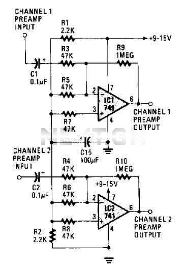
The circuit operates using two 741 operational amplifiers and achieves a gain exceeding 20 dB in each channel. Utilizing a higher-quality op-amp can improve the noise figure and bandwidth. Additionally, the circuit features a sharp roll-off at 20,000 Hertz. This...
A cathode follower based on the 6BL7 or 6BX7 is ideal for output. I used a mu-follower circuit with no feedback, a 12SN7 as the gain stage, and a 6BL7 as the cathode follower/current source. You might argue that...
The preamplifier in question is engineered to interface with various audio devices such as CD players, tuners, and tape recorders. Its primary function is to provide an alternating current (AC) voltage gain of 4, an attribute that allows it to...
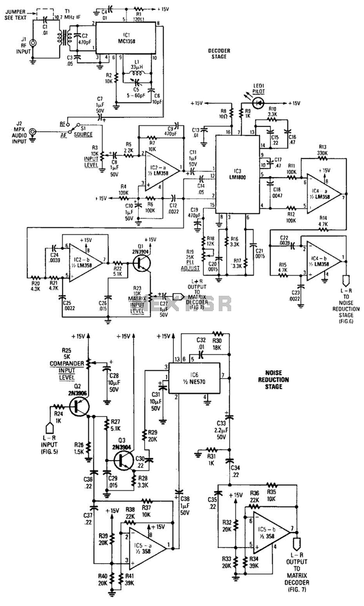
A block diagram of the stereo-TV decoder illustrates the overall relationships between the distinct sections of the circuit, while additional details of each subsection are provided. The decoder section is centered around TCI, a standard 4.5-MHz audio demodulator. The...
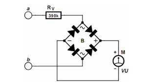
Using an old moving coil instrument, it is quite easy to create a simple voltmeter that visually indicates the status of a telephone. A simple voltmeter can be constructed using an old moving coil instrument, which is a type of...