
Parking Indicator for Automobile

The circuit utilizes a 1N1418 diode, which is a standard rectifier diode known for its reliability and efficiency in various applications. The primary function of this circuit is to provide visual feedback to the driver during parking maneuvers, enhancing safety and precision.
The schematic typically includes a microcontroller or a simple logic circuit that processes input from proximity sensors installed around the vehicle. These sensors detect obstacles and relay the information to the circuit. Based on the distance measured, the circuit activates an indicator light or a series of lights that change in intensity or color, depending on how close the vehicle is to an obstacle.
For instance, as the vehicle approaches an object, the indicator may shift from green to yellow and finally to red, signaling the driver to stop. The integration of the 1N1418 diode ensures that the circuit operates efficiently by preventing reverse current flow, which could damage sensitive components.
In addition to the diode, the circuit may also incorporate resistors for current limiting, capacitors for smoothing voltage fluctuations, and possibly a transistor to drive the indicator lights if higher current is required. Proper layout and connections are essential to ensure that the circuit functions reliably under varying environmental conditions, such as temperature fluctuations and vibrations experienced while driving.
This parking aid circuit represents a valuable enhancement for vehicle safety, particularly in urban environments where visibility can be compromised.The circuit was designed to produce an indicator to aid a car from parking especially in places without clear visibility. 1N1418 . 🔗 External reference
Related Circuits
This circuit indicates the water level in an overhead tank and activates an alarm when the tank is full. It utilizes the commonly available CD4066 bilateral switch CMOS IC to display the water level through LEDs. When the tank...
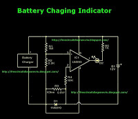
This is a battery charger indicator circuit diagram. When the battery is charging, it is indicated by an LED. This circuit can be used with a 12V battery with a charging current of less than 1A. The battery charger indicator...
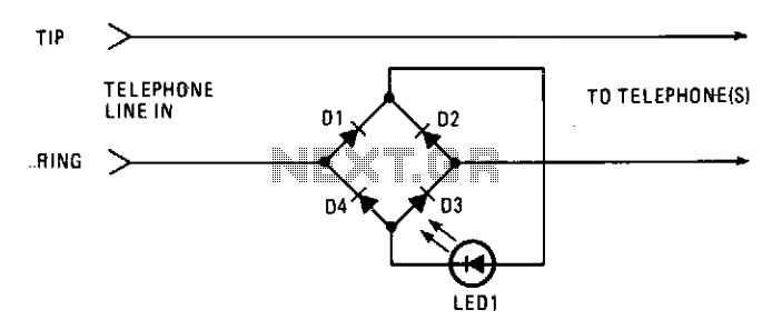
This circuit operates as a line-current sensor and can be connected in series with any of the phone lines. To indicate an "in use" status for all phones on a single line, it must be connected in series with...

If a lead-acid battery is not used for an extended period, it experiences self-discharge at a rate of 4% per week at 27 degrees Celsius. For instance, a 125 Ah tubular battery discharges at a rate of 5 Amps...
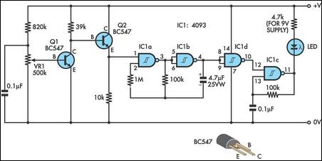
This design integrates power-on and low-battery indication features, capable of operating with any battery voltage up to 15V. It has a very low current drain of 2mA or less and is cost-effective, priced under $3.50 with new components. When...
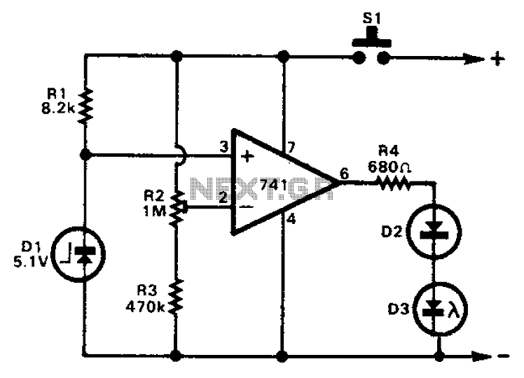
The 741 operational amplifier can function as a voltage comparator. It features a non-inverting input and a Zener-controlled voltage source, with a reference voltage set at 5.1V. Resistor R2 is used to adjust the in-phase input voltage to half...