
Stereo balance meter

The circuit described utilizes a differential amplifier configuration to compare the outputs from two audio channels. The first integrated circuit (IC1) functions as a differential amplifier, processing the audio signals from the left and right channels. The output from IC1 is critical, as it determines the behavior of the subsequent integrated circuits, IC2 and IC3, which serve as indicators of channel dominance.
The non-inverting inputs of IC2 and IC3 are connected directly to the output of IC1. This setup allows IC2 and IC3 to respond to the differential voltage produced by IC1. When the output of IC1 approaches the positive supply voltage, indicating that the right channel signal is stronger, both IC2 and IC3 will output high signals. This condition activates LED3, signaling that the right channel is dominant.
In contrast, if the left channel signal is stronger, the output of IC1 will be lower, causing IC2 and IC3 to output low signals. This will illuminate LED1, indicating the left channel's dominance. The circuit is designed to provide a visual representation of channel strength through the LEDs, enhancing user experience by clearly indicating which channel is leading.
In scenarios where both channels are equal in amplitude, the output from IC1 will yield a balanced differential signal. This results in IC2 outputting a high signal while IC3 outputs a low signal, which activates LED2. This feature allows users to easily discern when both channels are balanced, providing a comprehensive visual feedback mechanism for audio signal management.
Overall, this circuit design effectively combines audio processing with visual indicators, making it a valuable tool for monitoring audio channel performance in various applications.Outputs from each channel are fed to the two inputs of ICl connected as a differential amplifier. IC2 and 3 are driven by the output of ICl. Output of ICl is connected to the noninverting inputs of IC2 and 3. If the output of ICl approaches the supply rail, the outputs of ICs 2 and 3 will also go high, illuminating LED3. This would happen if the right channel were dominating If the left channel was dominant, the outputs of ICs 2 and 3 would be low, illuminating LED1. If the two channels are equal in amplitude, the outputs of ICs 2 and 3 would be high and low respectively, lighting up LED2.
Related Circuits
The frequency formula of a 555 oscillator is well-known. For given resistors and capacitors, the frequency can be calculated using a specific formula derived from mathematical principles. The 555 timer IC is widely used in various applications, including oscillators, timers,...
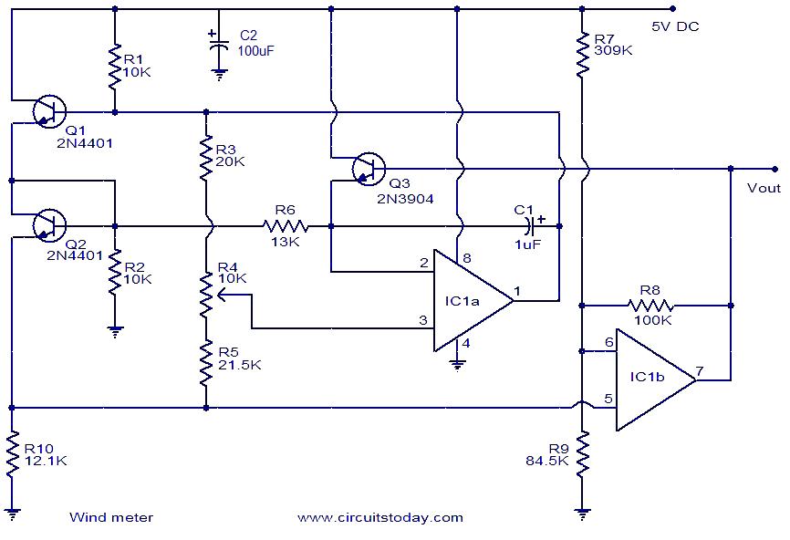
This is a simple wind meter (anemometer) circuit. While accuracy cannot be guaranteed, the circuit functions adequately. It can measure wind speeds up to 75 m/s. Transistors Q1 and Q2 are employed for wind sensing, utilizing the relationship between...

This is a circuit design for a digital voltmeter with an LED display. It is suitable for measuring the output voltage of a DC power supply. The circuit features a 3.5-digit LED display with a negative voltage indicator and...
Comprehensive information regarding the RF Field Strength Meter Circuit is available. Users can learn about and download the RF Field Strength Meter Circuit online. The RF Field Strength Meter Circuit is designed to measure the strength of radio frequency (RF)...
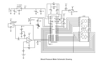
This digital circuit outlines a concept for a digital blood pressure meter that incorporates an integrated pressure sensor, analog signal conditioning circuitry, microcontroller hardware/software, and a liquid crystal display. The sensing system measures cuff pressure (CP) and extracts pulses...
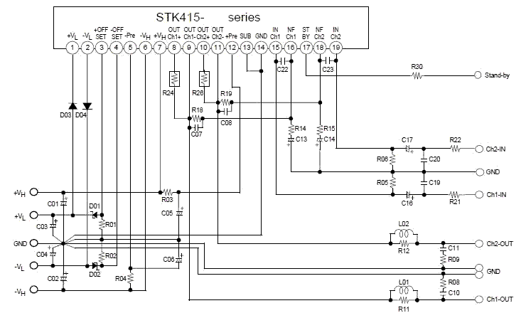
This electronic project stereo amp is based on the STK415-090-E class H audio power amplifier hybrid IC that features a built-in power supply switching circuit. This STK415-090-E class H audio power amplifier provides high efficiency audio power amplification by...