
Wind meter

This wind meter circuit employs a differential sensing method using two transistors (Q1 and Q2) to measure wind speed based on thermal cooling effects. The circuit operates by measuring the power dissipation differences between the two transistors, which are exposed to varying wind conditions. When wind flows over the transistors, Q1 experiences a greater cooling effect than Q2, causing its Vce to decrease relative to Q2. This change in Vce translates into a measurable voltage difference across resistor R10.
The op-amp in the circuit amplifies the voltage difference, producing an output voltage (Vout) that corresponds to the wind speed. The linearity of this relationship allows for straightforward calibration, with 0 V output indicating no wind and 2.5 V output indicating the maximum measurable wind speed of 75 m/s. To display the output voltage, a 3 V FSD voltmeter is integrated, providing a visual representation of the wind speed.
Precision in resistor selection is crucial, as the performance of the circuit heavily relies on accurate resistance values. Non-standard resistor values necessitate careful combination to achieve the desired circuit characteristics, ensuring reliable measurements. The design may be further enhanced by incorporating additional filtering or calibration techniques to improve accuracy and stability under varying environmental conditions. Overall, this wind meter circuit demonstrates a practical application of thermal sensing using bipolar junction transistors in an accessible and effective manner.Here is a very simple wind meter (anemometer) circuit. I can`t guarantee much on the accuracy of this circuit but it circuit works quite fine. You can measure wind speeds up to 75m/s using this circuit. The transistors Q1 and Q2 are used for sensing the wind. The relationship between thermal impedance of the transistor and the surrounding wind spe ed is utilized here. Transistors Q1 and Q2 are wired so that the Vce of Q1 is higher than Q2 and therefore there will be a higher power dissipation. The wind causes cooling and so the Vce of Q1 changes. The ends in different power dissipations and different voltages across R10. This variation is detected by the opamp and amplified to produce the Vout which is proportional to the wind speed.
For still air Vout will be 0V and at 75m/s wind speed the Vout will be 2. 5V. A 3V FSD voltmeter connected across the Vout terminal and ground can be used as the display. Most of the resistors used here are not standard values. So you need to use the combination (series or parallel) of resistors to attain the specified values. Please note that the resistor values are very critical in this circuit. 🔗 External reference
Related Circuits

This simple wind charger circuit project is designed using the LTC1042 monolithic CMOS window comparator, manufactured by Linear Technology. The wind charger circuit utilizes wind power to generate the energy necessary for charging Ni-Cd or lead-acid batteries. When the...

The microampere meter provides full-scale deflection for a 0.1 V input. The current to be measured flows through a known resistor. The microampere meter is an essential instrument used for measuring very low currents in the microampere range. It operates...
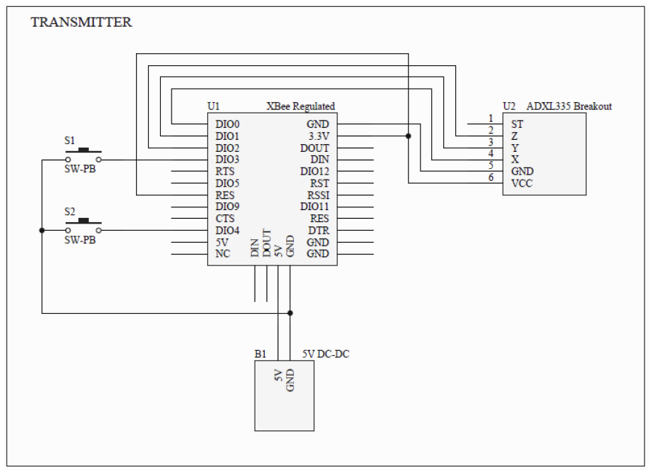
The present document shows step by step how to easily build an interesting pointing device: the wireless tilt mouse, that allows to control the mouse's cursor on the PC screen through the tilt of the board itself. The analog...

This circuit utilizes a DC amplifier (LM324) in a bar-graph configuration that employs an LM339 quad comparator integrated circuit (IC) to detect DC levels. The LEDs illuminate for every 100 mV increase. The LM324 operational amplifier is set up...

This design measures the differential temperature between two sensors. Sensor T1, located before the heater resistor, measures the fluid's temperature prior to heating by the resistor. Sensor T2 detects the temperature rise induced in the fluid by the resistor's...
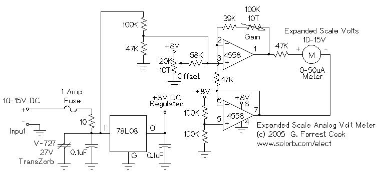
This circuit is designed to measure the voltage of a 12V nominal lead-acid rechargeable battery system. While it was specifically created for solar-powered systems, it is versatile enough for use in automotive or other 12V applications. Lead-acid batteries typically...