
Stereo balance meter

To implement a system that allows for the playback of stereo discs or tapes in mono mode, the circuit must include an amplifier capable of processing both stereo inputs. The amplifier should have a mono switch that combines the left and right channels into a single output.
The circuit design would typically involve two input channels, each connected to a potentiometer for adjusting the balance. These potentiometers will allow for fine-tuning of the left and right audio levels before they are mixed. The outputs from the potentiometers feed into a summing amplifier, which combines the signals into one mono output.
In this configuration, a meter (Ml) is employed to provide feedback on the balance adjustment. The meter is connected to the output of the summing amplifier and is calibrated to indicate zero when the left and right channel levels are equal. The user will adjust the potentiometers until the meter reads zero, ensuring that the output levels are identical.
This setup is essential for applications where stereo separation is not desired, such as in mono audio systems or when listening to recordings that were originally mixed in mono. Proper implementation of the balance adjustment ensures optimal sound quality and uniformity in audio playback.Play any stereo disc or tape and then set the amplifier to mono Adjust left and right channel balance until meter Ml indicates zero; then the left and right output level are identical.
Related Circuits
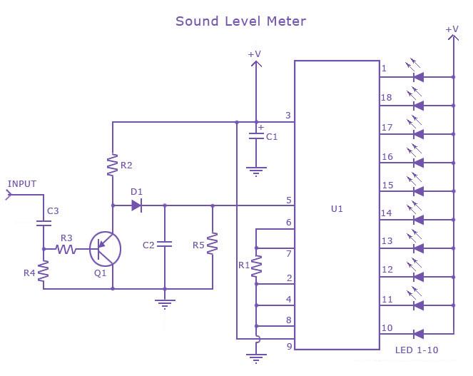
This is a single-chip sound level meter that can be used to display the sound level of an amplifier or simply the sound level from a microphone. The core component of the circuit is the IC LM3915 Audio Level...
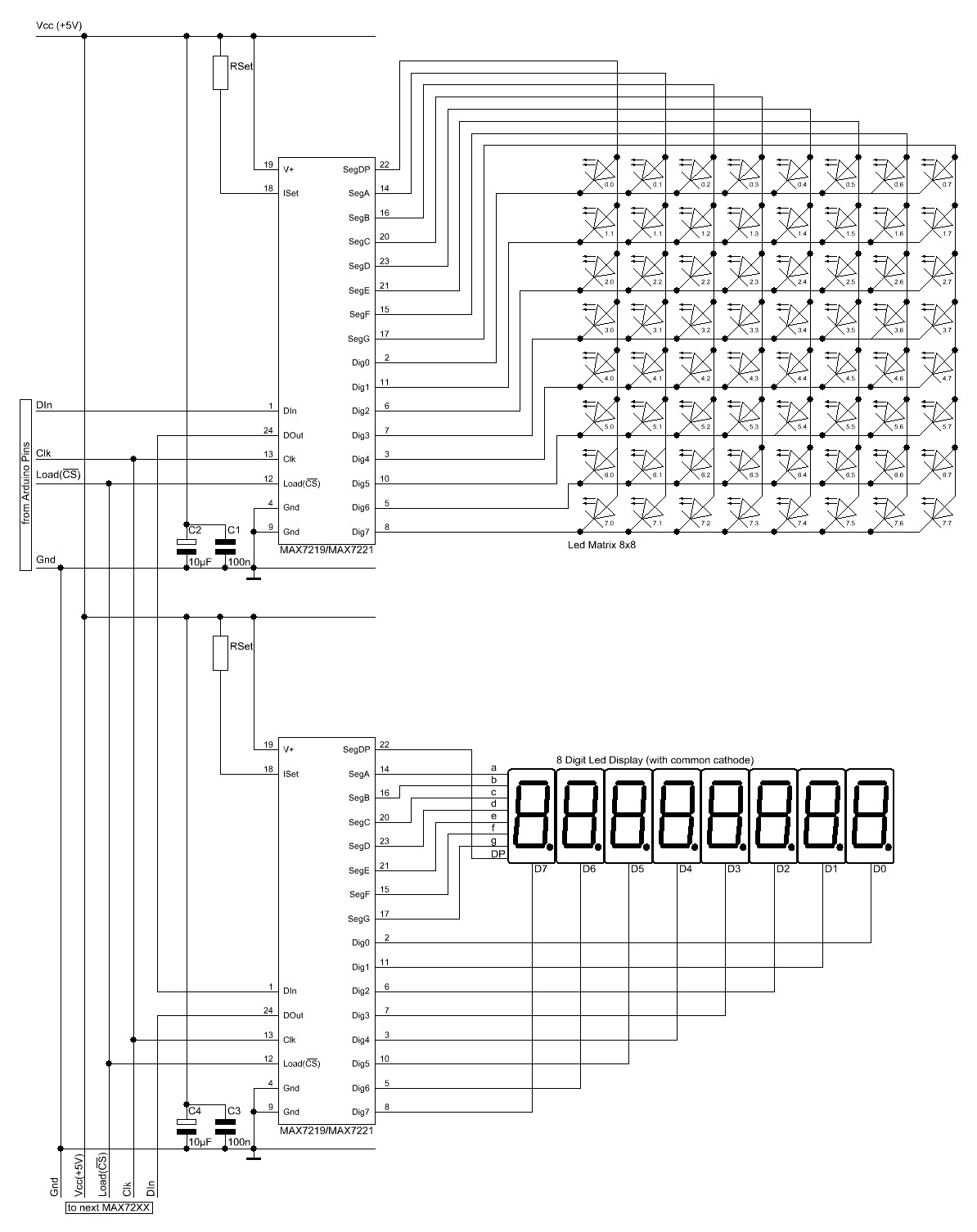
The Arduino website provides comprehensive documentation on connecting LEDs to the Arduino using the MAX7221. A specific set of components is required for this setup. The MAX7221 is a versatile LED driver that enables the control of multiple LEDs through...
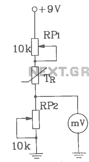
T-121 temperature sensor electronic thermometer circuit diagram shown below The T-121 temperature sensor circuit is designed to measure and display temperature readings accurately. The circuit typically consists of a temperature sensor, such as the T-121, which converts temperature variations into...
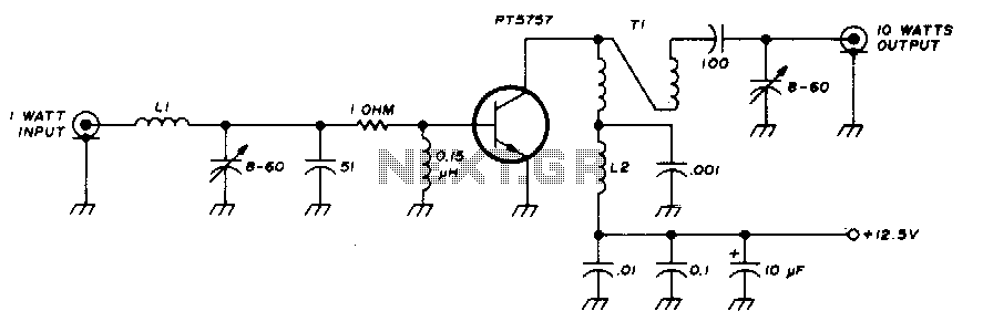
This 10-watt, 144-MHz power amplifier utilizes a TRW PT5757 transistor. The inductor LI consists of 4 turns of no. 20 enameled wire with a 3/32" inner diameter, while inductor L2 comprises 10 turns of no. 20 enameled wire with...
This Hartley oscillator was constructed using a single 45 tube and is based on a design published in a 1932 QST article by George Grammer. The initial circuit experienced performance issues due to weak 45 tubes, necessitating a very...
The multimeter should be set to the lowest DC volts range for maximum sensitivity, typically 200mV DC for most meters. The circuit operates effectively at VHF frequencies, approximately 100MHz, yielding satisfactory results. The inductor L1 consists of 7 turns...