
Stereo decoder circuit using MC1310P

The FM stereo decoder circuit based on the MC1310P IC is designed to demodulate FM stereo signals efficiently while ensuring high fidelity audio output. The MC1310P is a versatile and widely used IC that integrates various functions necessary for stereo FM demodulation, including the processing of multiplexed audio signals.
The circuit typically operates with a power supply of 12V, which is standard for many consumer electronics, ensuring compatibility with a wide range of FM receiver applications. The 40dB channel separation is a critical specification, as it indicates the ability of the circuit to distinguish between the left and right audio channels. This separation is essential for delivering a clear and immersive stereo sound experience.
In the implementation of this circuit, the MC1310P requires external components such as resistors, capacitors, and inductors to form the necessary filters and to set the appropriate operating parameters. The input stage usually involves an RF front-end that captures the FM signal from an antenna, which is then fed into the MC1310P for demodulation.
Output from the MC1310P can be directly connected to audio amplifiers or further processing stages, depending on the design requirements. The circuit's architecture allows for adjustments in gain and filtering to optimize audio quality and performance, making it adaptable for various applications in stereo FM receivers.
Overall, this simple FM stereo decoder circuit is an effective solution for converting FM signals into high-quality stereo audio, suitable for both hobbyist projects and commercial audio applications.Simple FM stereo decoder circuit using MC1310P IC. 12V operation, 40dB channel seperation. Suitable for stereo FM receivers.. 🔗 External reference
Related Circuits
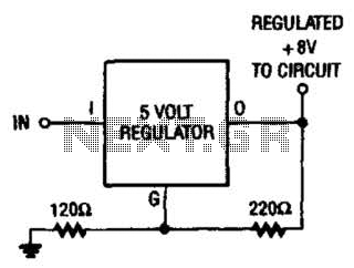
If locating an 8-V regulator proves difficult, a 5-V unit can serve as a replacement by connecting the regulator as illustrated here. In electronic circuits, voltage regulators are essential components that maintain a constant output voltage regardless of variations in...

The schematic illustrates the design of a circuit that measures the resistance of the skin and transforms it into a functional switching signal. This circuit typically employs a resistive sensor, often referred to as a skin resistance sensor or galvanic...

This is an application circuit for calibration known as a high voltage AC calibrator circuit. A key aspect of sine wave oscillator design is the stable control of amplitude. In this circuit, the amplitude is stabilized through servo control,...

It consists of a 4047 low-power monostable/astable multivibrator, IC1, used in the astable mode to provide the timing pulses to control the flash rate of the LEDs. To accomplish the astable mode, pins 4, 5, 6, and 14 are...

For basic requirements, square wave inverters can be utilized as they are simple, low-cost, and easy to construct. However, pure sine wave inverters are preferred for driving inductive loads. This document discusses a simple low-power square wave inverter using...

A negative temperature coefficient thermistor is utilized as the temperature sensing element (Rt). The circuit includes a resistor (Ri), a resistor (Rs), a potentiometer (RP), and the thermistor (R) to form a temperature bridge. A differential amplifier is created...