
Stereo preamplifier with tone control

The TDA1524 is a versatile audio amplifier IC that provides a compact solution for stereo preamplification with tone control capabilities. The circuit primarily consists of the TDA1524 IC, several passive components, and the necessary potentiometers for user-controlled adjustments. The inclusion of potentiometers allows for tailored audio output, enhancing user experience through adjustable parameters such as volume and tonal balance.
In the proposed configuration, potentiometers R1 (volume), R2 (balance), R3 (bass), and R4 (treble) interface with the audio signal path. For those opting to eliminate the balance control (R2), the input and output connections can be made directly, effectively bypassing the potentiometer. The 100nF capacitor, which may cause confusion, typically serves as a coupling capacitor, ensuring DC blocking while allowing AC audio signals to pass through. When omitting the balance control, it is essential to maintain the integrity of the signal path, which may involve placing the capacitor in series with the direct connection to avoid any unintended frequency response alterations.
The design's compatibility with single supply power amplifiers is a notable advantage, as it simplifies the power supply requirements and enhances the circuit's versatility. It is crucial to adhere to the manufacturer's guidelines regarding power supply voltage to ensure optimal performance and prevent distortion. The recommendation against using dual supply amplifiers stems from the potential for increased distortion, which can compromise sound quality.
Overall, the TDA1524-based preamplifier circuit represents a robust solution for audio applications, providing essential features while maintaining a straightforward design that is easily modifiable to suit specific needs.Here is the circuit diagram of an excellent stereo preamplifier with tone control using the IC TDA1524 from Phillips. The IC requires very few external components, has very low noise and has a wide power supply voltage range.
POTs R1 to R4 can be used for controlling the volume, balance, bass and treble respectively. LED is D1 is a power ON indica tor and R1o is its current limiting resistor. This is a good circuit. And i want to make this. But i don`t want the balance control. So how can i avoid that pot. I know that all i have to connect the in and out without the pot, but the 100nF cap is confusing me. Hi Anil I have assembled this way back in early 90s a nice circuit with very good quality and control range, with Philips application 40 watt circuit. This circuit is with single supply, hence you can use with single supply power amplifier. motional feed back amplifier is most suited for this chip. Do not try to use this dual supply power amplifiers you will end up with heavy distortion of reproduced sound.
🔗 External reference
Related Circuits
The LM1036 is a DC-controlled circuit designed for tone adjustment (bass/treble), volume control, and balance. It is suitable for use in car radios, televisions, and audio systems. The circuit also incorporates loudness compensation. The LM1036 integrates several functionalities essential for...
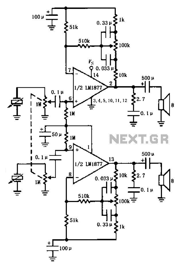
A bass player setup utilizing a stereo control is implemented through an LM1877 amplifier circuit. A cermet stereo microphone pickup is used to capture audio signals from a stereo turntable, with left and right channel outputs. The audio signals...

This stereo amplifier utilizes the NE5517/A and features an excellent tracking accuracy of 0.3 dB, which is typical. The offset can be adjusted using the potentiometer, Rp. For AC-coupled amplifiers, the potentiometer can be substituted with two 5.1 k...
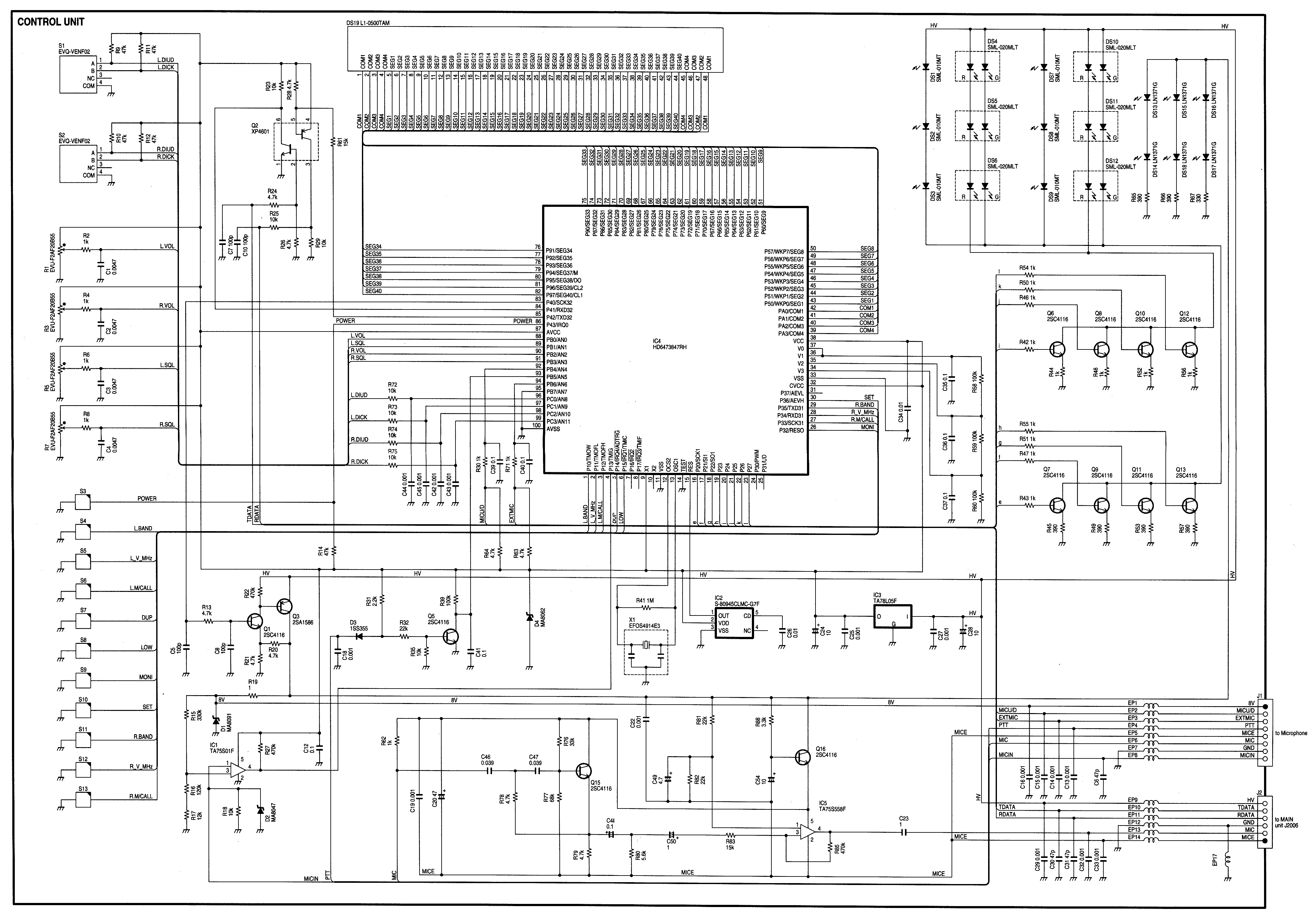
Radio Control Circuits PDF Manual Download. This document serves as a comprehensive guide to radio control circuits, intended for individuals seeking to understand the principles and applications of radio frequency (RF) technology in controlling various devices. The manual covers fundamental...
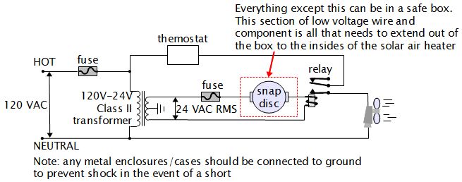
For various experiments, such as solar air heaters, an automatic fan activation and deactivation system is required. A straightforward solution is to use a bimetal snap disc thermal sensor. This sensor functions as a switch that closes when a...
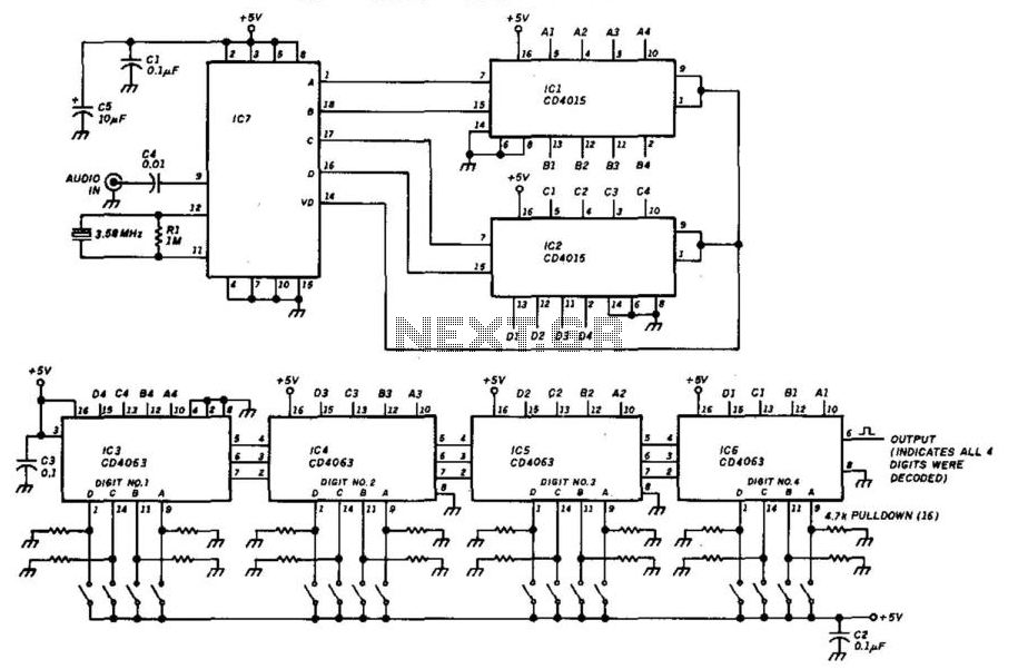
This decoder will respond to a preselected 4-digit DTMF number. IC7 is a Radio Shack IC device (part #276-1303). The logic is all CMOS. The digits are selected by SW1 and SW2, a pair of 8-position DIP switches. The described...