
STHS Computer Technology

To create an effective H-bridge circuit for controlling DC motors, it is essential to understand the basic configuration and operation of the components involved. An H-bridge consists of four switches (transistors or MOSFETs) arranged in an "H" shape, allowing current to flow in either direction through the motor, thus enabling forward and reverse rotation.
In this setup, the Arduino will control the H-bridge by sending signals to the gates of the transistors. When one pair of transistors is activated, the motor will rotate in one direction, while activating the other pair will reverse the motor's direction. The control signals can be generated using digital output pins from the Arduino, with one pin dedicated to each direction of the motor.
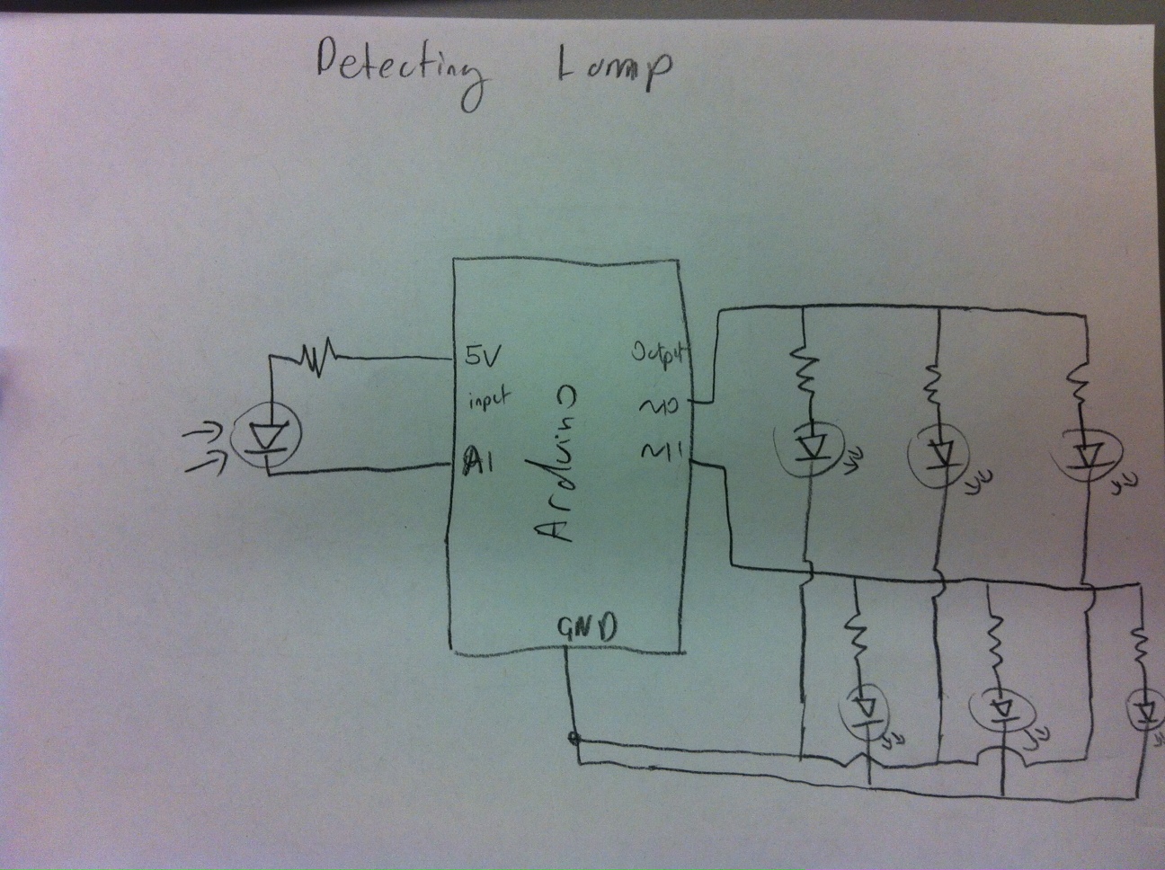
For the QRD line sensors, the circuit typically includes an infrared LED and a phototransistor. The LED emits infrared light, which reflects off the surface below it. The phototransistor detects the reflected light. When the sensor is over a dark line, less light is reflected, resulting in a lower signal at the phototransistor's output. Conversely, when the sensor is over a lighter surface, more light is reflected, yielding a higher output signal.
To ensure reliable operation, the Arduino must read the sensor values and establish a threshold. By determining the highest and lowest values from the sensors, the midpoint can be calculated and used as the threshold value. This threshold will allow the robot to make decisions based on the sensor readings, enabling it to follow the line accurately.
Testing of both the H-bridge circuits and the QRD line sensors is crucial. For the motors, the Arduino sketch should be modified to test each motor's functionality in both directions, ensuring proper operation. For the QRD sensors, the Arduino should continuously read values and compare them against the established threshold to maintain accurate line following behavior. Proper calibration and testing will ensure the robot performs as intended, effectively navigating its environment.On the breadboard, build two bi-directional motor control circuits (also known as "H-bridge") circuits. These circuits will control the two DC motors that drive the wheels. Each circuit will have two wires from the Arduino (one for forward, one for backward) to control the circuit, and two wires from the single DC motor that it is controlling.
You should test your circuits to ensure you can control both motors in both forward and reverse directions. Here is a sample Arduino sketch you can use to test the motors. Edit the code to check each motor and direction, and double-check the circuit for any motor that doesn`t behave as expected.
Here`s the schematic circuit diagram of one QRD line sensor connected to the Arduino. You will be wiring two of these, so your robot can tell whether it is on the line, off a little bit to the left, off a little bit to the right, or completely off the line. Now test that both QRD1114`s are operating correctly, and sending a proper signal to the Arduino. Here is a sample Arduino sketch to test the circuits. Make sure you are getting a good range of values from both sensors between light and dark. Make a not of the highest and lowest values you get from each sensor. You will use a value half way in between these for your "cut off" or "threshold" value. This is the boundary value we`ll use to decide if the sensor is seeing the dark line or not. 🔗 External reference
Related Circuits

This text discusses the MSC1210 microcontroller as the core of a high-accuracy temperature measurement system, which includes signal processing and communication capabilities. The system is designed for easy expansion, allowing for accurate measurements and fast data acquisition. The hardware...
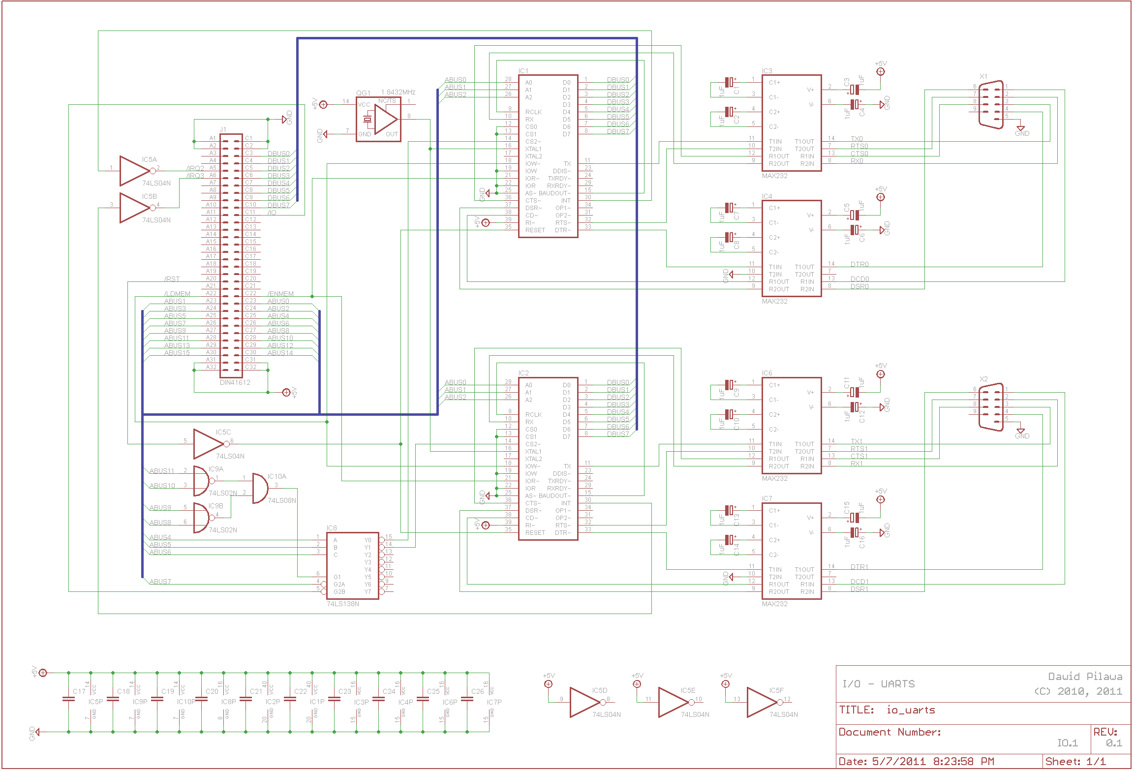
A functional interrupt-driven RS/232 driver is currently in operation, supporting hardware flow control at a baud rate of 9600 bps. Although higher baud rates are achievable, stability has yet to be verified. Helper routines have been developed to facilitate...

Designing a wide-range variable power supply using a linear regulator is straightforward; however, it suffers from poor efficiency when regulating a constant 60-volt source. A wide-range variable power supply can be implemented using a linear regulator, which allows for adjustable...
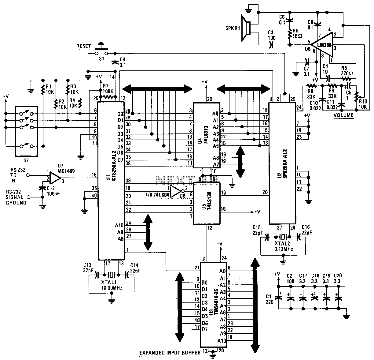
This text-to-speech converter is constructed using the SP0256-AL2 speech processor and the CF6256AL2 text-to-speech converter chips manufactured by General Instruments. The circuit is designed to receive standard ASCII code from virtually any microcomputer or dumb terminal equipped with an...
A habit-acquisition system that tags physical objects, such as dumbbells and medicine bottles, with RF tags or microcontrollers to detect and log user interactions with these items. It includes virtual plants and creatures that simulate the health of real-world...

This circuit was designed by Lazar Pancic from Yugoslavia. A typical PC sound card includes a microphone input, speaker output, and occasionally line inputs and outputs. The microphone input is specifically tailored for dynamic microphones with an impedance range...