
street light lamp circuit

The automatic street light circuit primarily consists of a light-dependent resistor (LDR), two 2N3904 NPN transistors, a relay, and a variable resistor (VR) for sensitivity adjustment. The LDR plays a critical role in detecting ambient light levels. In bright conditions, the LDR's low resistance allows current to flow, keeping transistor Q1 in the off state, which in turn keeps Q2 off, preventing the relay from activating. As ambient light decreases at dusk, the LDR's resistance increases, which raises the voltage at the base of Q1, turning it on. This action also turns off Q2, allowing the relay to engage and power the connected load.
The circuit can be powered by a DC source of 6V, 9V, or 12V, with the relay being rated for the same voltage to ensure compatibility and proper operation. The variable resistor (50K VR) allows for fine-tuning of the light sensitivity, enabling the user to set the threshold at which the circuit activates based on the local lighting conditions.
The relay used in the circuit acts as a switch to control the higher voltage AC load. It is essential to select a relay that can handle the maximum load current and voltage to prevent damage or failure of the circuit. The simplicity of the design allows for easy assembly and troubleshooting, making it an excellent choice for DIY enthusiasts looking to automate outdoor lighting solutions.Here is a very useful project of an automatic street light or lamp circuit which can be used to activate your outdoor lights like garden lamps, night lights etc. automatically when the sun set and turn off automatically when the sun rises. The circuit is quite sensitive and versatile and can be used to activate any 220 volt AC device at night and
turn off in day all you have to do is simply connect the device with the load point. You can also connect a 220V plug socket with the load point to connect different electronic devices but make sure the relay points can able to handle the provided load. The circuit is simple using two 2N3904 transistors and few other components. The 50K VR (Variable Resistor) is used to adjust the circuit to activate the relay on the required darkness.
The circuit can be operated with 6 volts, 9 volts and 12 volts but it is important to use the same voltage relay also. The circuit is actually a dark detecting circuit or we can also say it dark / light sensor circuit. The two transistor used in the circuit are working as switches. When light falls on the LDR its resistance decreases and the voltage at the base of Q1 will increase which will switch on the Q1 and the Q2 will remain switch off.
When there is no light on the surface of the LDR its resistor increases, which will switch off the transistor Q1 and the voltage at the base of Q2 increases and hence the transistor Q2 will switch on and activates the relay switch. 🔗 External reference
Related Circuits

This design utilizes standard metal gate CMOS logic rather than the typical PIC or custom chip. A 22µF capacitor charges during one half of the AC cycle and provides trigger current to the triac during both halves. The circuit employs...

A simple technique for measuring frequencies across a wide range with acceptable accuracy limits using a PC is presented. This method follows the basic principle of measuring low frequencies, where the period of a complete wave is measured and...
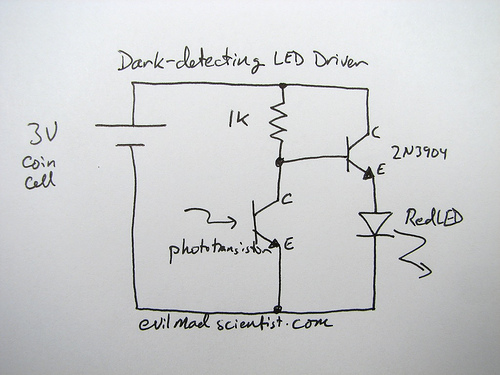
A circuit that uses a phototransistor to create a light-sensitive switch. When there is no light in the room, the LED connected to the phototransistor lights up, and when there is light, the LED turns off. Any schematic or...
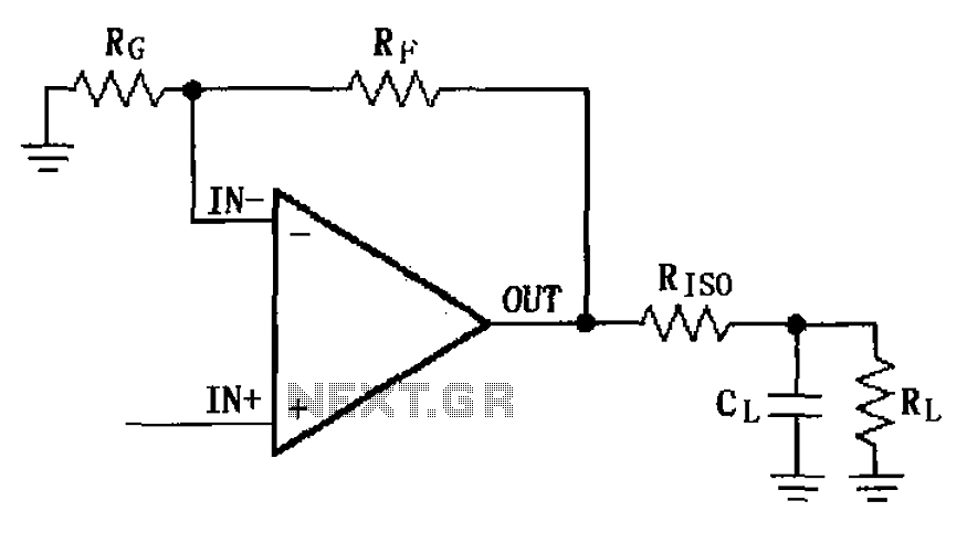
The MAX4223 to MAX4228 series incorporates a capacitive load drive circuit with an isolation resistor (RISO). The maximum allowable capacitive load for these devices is 25pF. However, exceeding this limit can lead to overshoot and ringing. The circuit design...
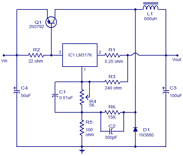
This circuit illustrates a 3A Switching Regulator Circuit based on the LM317K integrated circuit. It is designed to be simple and cost-effective. The 3A Switching Regulator Circuit utilizing the LM317K IC serves as a versatile voltage regulation solution, capable of...
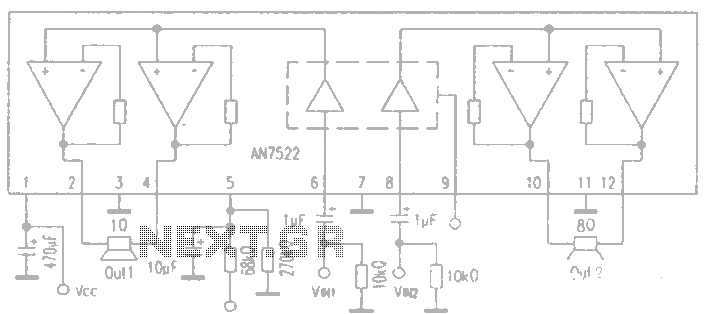
AN7522 is a Panasonic stereo audio amplifier IC that delivers an output power of 3W at 8 ohms. It features a standby function, low static power consumption, and reduced noise levels, requiring fewer external components for stable operation. This...