
Strong excitation DC electromagnet rapid pull-ter a circuit

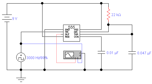
The operation of a capacitor discharge circuit involves the release of stored electrical energy from a capacitor through a load, which can be resistive, capacitive, or a combination of both. In a resistive discharge circuit, the capacitor discharges through a resistor, resulting in a predictable exponential decay of voltage over time, governed by the time constant τ (tau), which is the product of resistance (R) and capacitance (C). The voltage across the capacitor can be described by the equation V(t) = V0 * e^(-t/τ), where V0 is the initial voltage and t is the time elapsed since discharge began.
In a capacitive discharge circuit, the capacitor may discharge through another capacitor, leading to a more complex interaction. The discharge profile will depend on the capacitance values and the configuration of the circuit. The strong excitation method refers to the rapid application of voltage or current to the circuit, which can enhance the discharge rate and efficiency. The longer the strong excitation time is maintained, the more significant the energy transfer can be, allowing for a more substantial impact on the circuit's performance.
The design considerations for such circuits include selecting appropriate resistor and capacitor values to achieve the desired discharge characteristics, ensuring that components can handle the energy levels involved, and incorporating safety mechanisms to prevent damage from excessive current or voltage spikes. Proper simulation and testing are essential to validate the circuit's performance before implementation in practical applications. Both resistive and capacitive type capacitor discharge circuit is the use of the method of strong excitation. Capacitor C capacity, the longer the strong excitation time.
Related Circuits
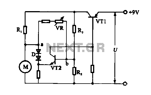
The electronic circuit for steady speed motor applications utilizes an automatic remote control system to regulate the motor power supply, thereby achieving consistent speed control. The circuit diagram illustrates a DC motor connected to the system. Given that the...
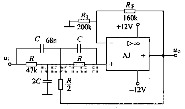
A band-stop filter (BSF) utilizing an integrated operational amplifier is designed to suppress signals within a specific frequency band, allowing signals outside this band to pass with minimal attenuation. This configuration is achieved through a two-stage network, which employs...
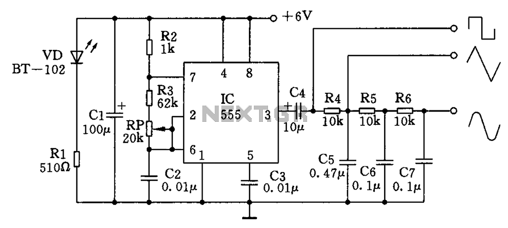
The circuit simultaneously generates a square wave, triangle wave, and sine wave, making it particularly suitable for electronics enthusiasts and students who wish to observe signal waveforms using an oscilloscope. This signal generator circuit is simple, low-cost, and allows...
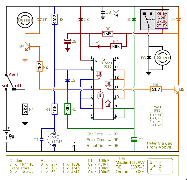
This is an improved version of the basic Garage/Shed Alarm. The Entry and Exit delays have been extended to approximately 30 seconds, and a timed Siren cut-off along with an automatic reset feature has been added. Additionally, the LED...
A simple 3-way crossover, intended for triamping Hi-Fi systems. This is a conventional 12dB / Octave unit, and cannot be expected to have the same performance as a Linkwitz-Riley aligned filter network. It will still be a vast improvement...
The standard assumption is that the phase shift sections operate independently. According to the equation provided, the loop phase shift reaches -180 degrees when the phase shift of each section is 60 degrees. This condition is met when ω...