stun gun

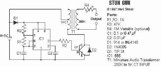
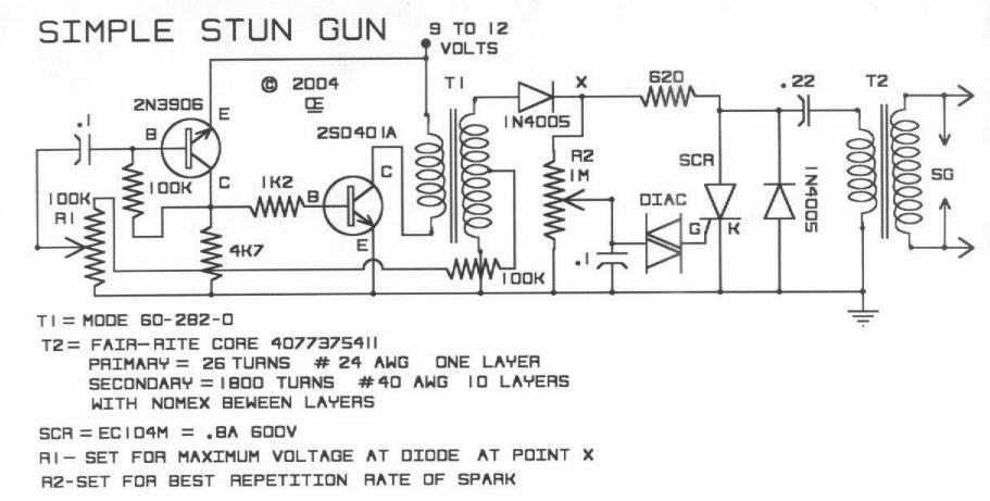
This circuit generates a very high voltage, and precautions must be taken to avoid electric shock. The transformer can generate over 1,000 volts, while the 8-stage multiplier can produce up to 20,000 volts.
This high-voltage circuit typically consists of a step-up transformer and a voltage multiplier circuit. The transformer is designed to convert a lower AC voltage into a significantly higher AC voltage. Its primary winding is connected to a standard power source, and the secondary winding is configured to deliver an output exceeding 1,000 volts.
The 8-stage voltage multiplier is commonly composed of a series of capacitors and diodes arranged in a specific configuration to achieve the desired output voltage. Each stage of the multiplier increases the voltage by a factor determined by the number of stages and the input voltage. In this case, the configuration allows for an output voltage of up to 20,000 volts, which is achieved through a cascading effect where each stage contributes to the overall voltage increase.
Safety measures are critical in circuits of this nature due to the risk of electric shock. Proper insulation, secure connections, and the use of protective enclosures are essential to safeguard against accidental contact with high-voltage components. Additionally, implementing discharge circuits and warning signage can further enhance safety when working with or around such high-voltage systems.
Overall, this type of circuit finds applications in various fields, including high-voltage testing, particle accelerators, and other specialized electronic devices that require high voltage for operation.This circuit produces a very high voltage and care must be used to prevent getting a nasty shock. The transformer can produce over 1, 000v and the 8-stage multiplier can produce up to 20, 000v 🔗 External reference


