
Stun Gun with 555

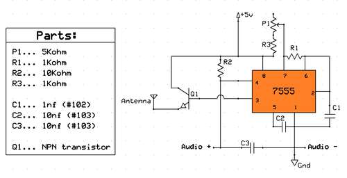
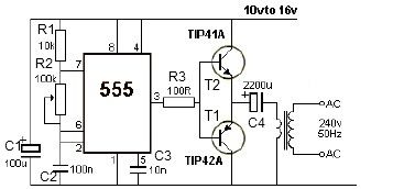
The circuit operates on a 9V battery, which serves as the primary power source. The 555 timer integrated circuit (IC) is configured in astable mode to produce a square wave signal at a high frequency, typically in the range of several kilohertz. This high-frequency output is essential for driving the transformer effectively, allowing it to step up the voltage.
The transformer utilized in this circuit is a high-voltage transformer designed to increase the voltage from the 9V input to approximately 1800V. It is crucial to note that while the voltage is significantly high, the output current remains low, which is a characteristic feature of stun gun circuits. This combination of high voltage and low current is what allows the device to deliver a painful shock without causing fatal harm.
In addition to the transformer, a 1 MEGΩ variable resistor can be integrated into the circuit at the output. This component serves as a means to adjust the output voltage, providing the user with the ability to control the intensity of the shock. However, the inclusion of this resistor is optional and may be omitted depending on the design preferences of the builder.
Safety precautions are paramount when constructing or handling this circuit. The high voltage output can induce a painful shock if contact is made with the output leads. Proper insulation and safety measures should be implemented to prevent accidental contact with the high-voltage components. It is recommended that individuals with adequate knowledge of high-voltage electronics should undertake the construction and testing of this stun gun circuit.This stun gun is powered by a 9V battery. The transformer steps up the voltage to about 1800V (but with very low current). A 555 timer IC is used to generate a high-frequency output. A 1 MEG variable resistor can also be used at the output to drop the voltage, but this is optional. If you build this circuit, be careful, as it outputs a high voltage. Touching the output leads will induce a painful shock. 🔗 External reference
Related Circuits
Planning to base a QRP transmitter on an instructables project, utilizing a large collection of 555 integrated circuits available. The issue is that this transmitter is designed to operate slightly below the commercial AM band. The goal is to...
Electronics tutorial about the 555 oscillator and how the 555 oscillator can be used as a 555 astable oscillator circuit to generate square wave waveforms. The 555 timer IC is a versatile and widely used component in electronics, particularly for...
Can anyone inform me whether the output of a monostable 555 timer circuit can be utilized to trigger another similar timer circuit? I have illustrated my concept with a... The monostable 555 timer circuit is a versatile component widely used...
This circuit receives a Doppler signal from a radar, amplifies and limits it, and then feeds the frequency into a counter (U4) and a display circuit (DISP1, DISP2, U5, U6). The calibration of the counter is determined by the...
A basic square wave generator has been designed to operate a speedometer circuit board, which is responsible for controlling various functions. The square wave generator circuit typically consists of a few key components: a timer IC, such as the 555...
This 12V power inverter circuit can be utilized to power small devices that require 240 volts. It is particularly advantageous for operating 240-volt appliances using a 12-volt car battery. Unlike typical feedback oscillator inverters, this design employs a 555...