
Stylophone schematic Electronic marvel from years ago

The schematic for the Stylophone 350 illustrates a unique electronic music instrument that operates without the commonly used 555 timer, often found in similar devices. The absence of a DIP-8 chip socket suggests that the design may utilize discrete components or alternative integrated circuits tailored for specific functionalities.
The Super Stylophone enhances the original design by incorporating duophonic capabilities, allowing it to produce two simultaneous notes, which expands the musical possibilities. The inclusion of multiple sound options suggests a versatile sound generation mechanism, likely based on analog synthesis techniques, which may involve oscillators, filters, and modulation circuits.
A notable feature of the Super Stylophone is the D-Beam controller, which utilizes a photocell as a sensor to detect hand movements. This innovative control method enables users to manipulate sound parameters in real-time, offering an interactive performance experience. The photocell's response to light levels can be calibrated to adjust various aspects of sound, such as pitch, volume, or effects, depending on the circuit design.
Overall, the schematic represents a significant advancement in electronic music instruments, showcasing both traditional synthesis methods and modern interactive controls, catering to musicians and enthusiasts seeking unique sound creation tools.I recently uncovered this schematic, that seems to be authentic and does not feature the 555 timer. Additionally if you check out the picture of Brian Davis on this page you can see him holding up the etch mask I don`t see anything that looks like a socket for a DIP-8 chip. (Schematic came from Sean Kerrigan`s page here ) The Stylophone 350 (Super Stylophone ) this one was duophonic, and had a bunch of different sounds, *and* the world`s first D-Beam controller a photocell that could be covered with the hand to modulate the sound further. Very cool. 🔗 External reference
Related Circuits
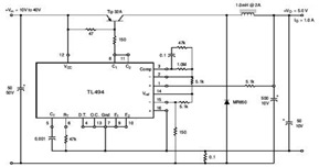
The circuit illustrates a TL494 pulse width modulated step-down converter schematic. This circuit allows for testing of line regulation, load regulation, output ripple, short circuit current, and efficiency under various input voltage conditions. A detailed table of these tests...
The power supply has been simplified. Power transformers and rectifiers have been omitted, and some components from the MOSFET voltage regulator circuits have been removed, including 1N5242 zener diodes between the source and gate and 10k resistors in series...

The Practical Shop Work Mark is based on productivity, work habits, safety, and cleanup while working on assigned projects or labs. Students will complete a Technical Activity Report detailing work accomplished at the end of each period, which will...
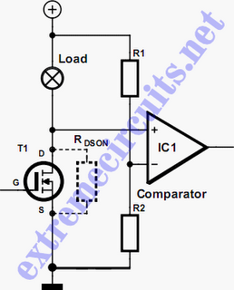
In applications where a MOSFET is used to switch a load, it is relatively straightforward to incorporate short-circuit or overload protection. This can be achieved by utilizing the internal resistance RDS(ON), which generates a voltage drop proportional to the...
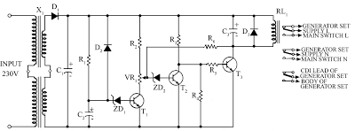
Due to the energy crisis, load shedding has become a common issue in several countries. Sudden power fluctuations, surges, and high voltage can damage sensitive household appliances such as TVs, VCRs, VCPs, and music systems. This circuit offers protection...
This circuit is designed for children's entertainment and can be installed on bicycles, battery-powered cars, motorcycles, as well as models and various games and toys. When switch SW1 is positioned as indicated in the circuit diagram, it generates the...