
The TL494 Datasheet and Pulse Width Modulated Step-Down Converter Circuit Schematic

The TL494 is a versatile integrated circuit commonly used in switch-mode power supplies and DC-DC converters. In this step-down converter configuration, the TL494 operates as a pulse width modulation (PWM) controller, regulating the output voltage by adjusting the duty cycle of the switching signal.
The circuit typically consists of the TL494 IC, a power MOSFET, an inductor, a diode, and several passive components such as resistors and capacitors. The inductor stores energy during the "on" phase of the PWM signal and releases it to the load during the "off" phase, allowing for efficient voltage regulation.
To evaluate the performance of the step-down converter, several tests can be conducted:
1. **Line Regulation:** This measures how well the output voltage remains constant despite variations in the input voltage. It is essential for ensuring stable operation in varying conditions.
2. **Load Regulation:** This test assesses the output voltage stability when the load current changes. Good load regulation indicates that the converter can maintain output voltage even with fluctuating load demands.
3. **Output Ripple:** This refers to the small, unwanted AC voltage superimposed on the DC output voltage. Measuring the output ripple is crucial for applications that require a clean and stable DC supply.
4. **Short Circuit Current:** This test determines the maximum current the converter can provide under short-circuit conditions. It is vital for assessing the safety and reliability of the circuit.
5. **Efficiency Test:** Efficiency is calculated by comparing the output power to the input power. High efficiency is desirable as it minimizes energy loss and heat generation.
These parameters can be evaluated under different input voltage conditions, providing a comprehensive overview of the converter's performance. The TL494 datasheet contains detailed tables and specifications that aid in understanding the expected performance metrics and assist in troubleshooting and optimizing the circuit design.The circuit shows TL494 Pulse Width Modulated Step?Down Converter Circuit Schematic. With this circuit you can have circuit test such Line Regulation, Load Regulation, Output Ripple, Short Circuit Current and Efficiency test with various Vin conditions. Detailed table of these tests are given in the TL494 datasheet. 🔗 External reference
Related Circuits
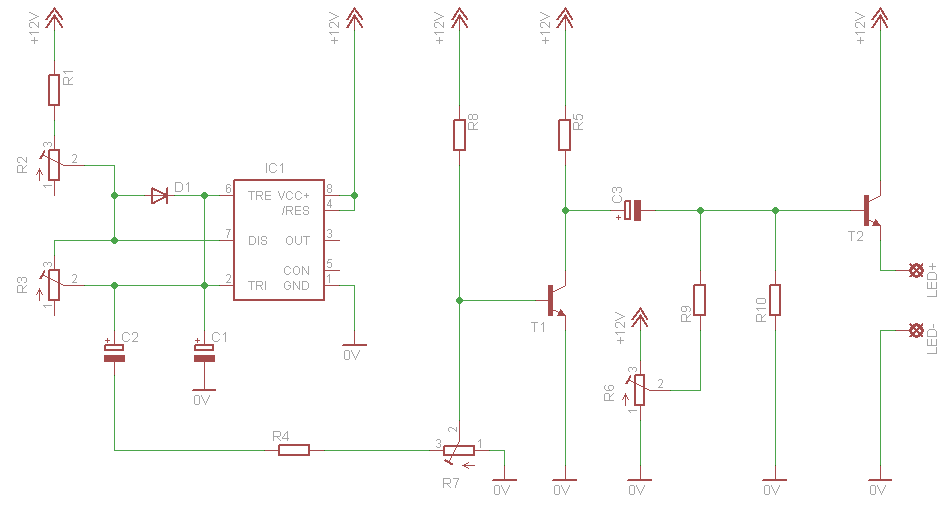
This circuit simulates a breathing or pulsing LED using a 555 timer chip. It has gained popularity, receiving numerous comments and emails from users who successfully built the circuit, as well as feedback from those who encountered difficulties when...
In the production of LCD projectors, the primary factor threatening the lifespan of the LCD screen is the temperature generated by halogen lamps. The multi-function controller designed by this circuit is highly effective for protecting liquid crystal projectors. The...
A request for a DIY 300BSE power amplifier schematic is made, with a specification to utilize Lowther PM6 speakers. The 300BSE power amplifier is a well-regarded audio amplification circuit known for its warm sound and high fidelity, particularly suited for...
This compact circuit enables automatic recording of phone conversations. It connects to the phone line, the microphone input of a tape recorder, and the remote control jack of the recorder. The circuit detects the voltage level in the phone...
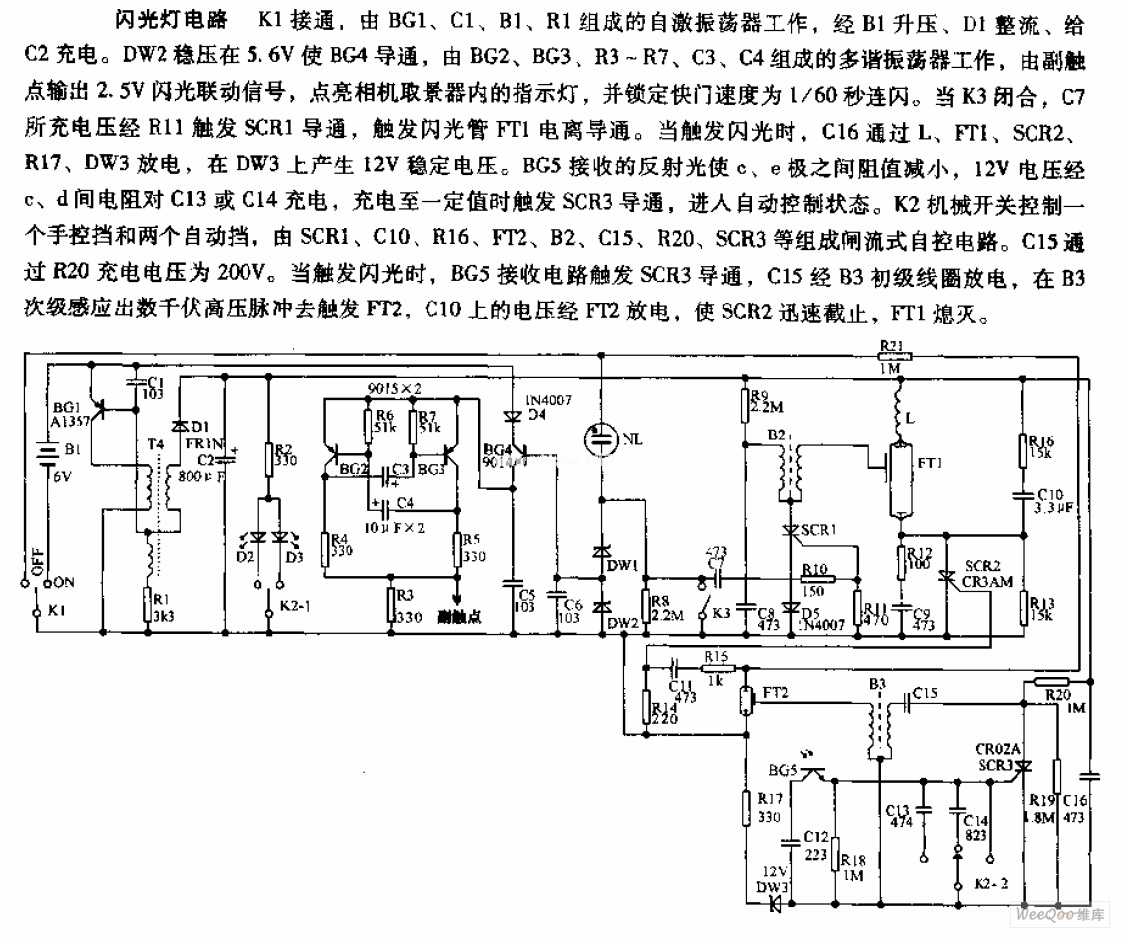
The camera flashlight circuit activates when switch K1 is engaged. This triggers a self-oscillating circuit consisting of BG1, capacitor C1, battery B1, and resistor R1. Once operational, the circuit boosts the voltage through B1 and rectifies it using diode...
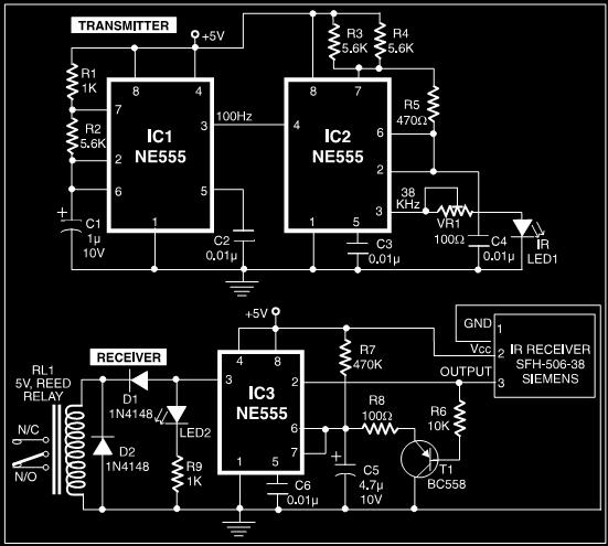
This post discusses a proximity detector circuit primarily utilizing the NE555 integrated circuit (IC). The circuit is designed for burglar alarms based on beam interruption, with the advantage that the transmitter and receiver are contained within the same enclosure,...