
Subwoofer Controller

The described circuit functions as a conventional phase control for audio applications, particularly suitable for subwoofer systems. The design employs a single operational amplifier (opamp), with a recommendation to utilize a dual opamp configuration to minimize source impedance. This is particularly beneficial when interfacing with other audio components, such as a crossover network, which may further enhance performance by allowing the omission of the initial stage if the driving source is adequately matched.
The TL072 opamp is specified due to its favorable characteristics, including low noise and sufficient bandwidth for subwoofer applications. The circuit's simplicity is a key feature, requiring no specialized components such as precision resistors or capacitors. The variable resistor, labeled VR1, serves as the phase control potentiometer, which should be of a linear taper to ensure smooth adjustment of the phase shift. The inclusion of a phase switch allows for easy selection of phase alignment, which can be critical in optimizing sound quality and coherence in multi-speaker setups.
Overall, the circuit's design reflects a straightforward approach to phase manipulation in audio systems, leveraging readily available components while ensuring compatibility with standard audio equipment. The implementation of this circuit can enhance the performance of subwoofers by allowing for precise phase adjustments, contributing to improved sound quality and listener experience.The circuit is completely conventional, and has been around almost forever in one guise or another. Similar circuits were used in the valve (tube) era, so there is nothing new about it. The circuit has already been published on these pages as a guitar tremolo circuit, but fairly obviously, that is not suitable for this purpose. The circuit uses one opamp, but a dual opamp is shown and recommended to ensure that the source impedance is low.
If driven from the output of a crossover (opamp based), the impedance will be fine, and the first stage may be omitted. There is nothing special about the circuit, and a TL072 opamp will be more than adequate for any subwoofer system. VR1 is the phase control pot, and should be linear. No special precautions or close tolerance resistors or caps are needed. The phase switch 🔗 External reference
Related Circuits
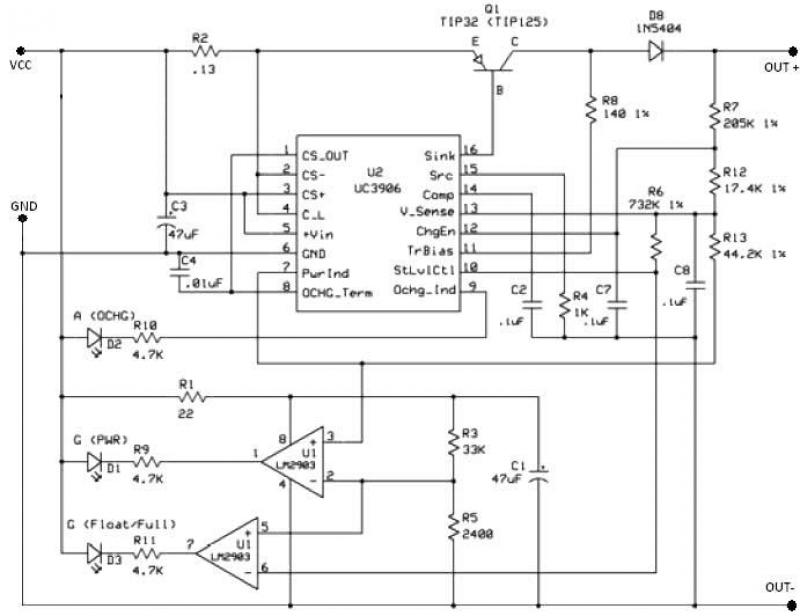
The UC3906 battery charger circuit controller includes all necessary circuitry to manage the charge and hold cycles for sealed lead-acid batteries. This circuit is specifically designed to deliver the appropriate charging voltage and current based on the battery's temperature...
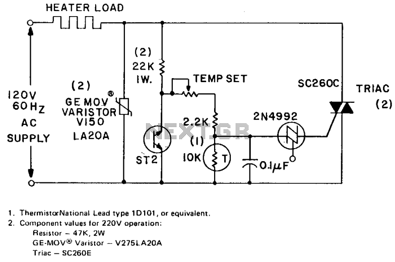
The circuit can control up to 6 kW of heating with moderate gain using a 25-amp triac (SC260D). Feedback is provided by a negative temperature coefficient (NTC) thermistor, which is positioned near the environment being temperature controlled. The temperature...
This temperature controller functions as a pulse snatching device, enabling it to operate at its own speed and activate at the zero crossing of the line frequency. The zero crossing activation minimizes the generation of line noise transients. A...
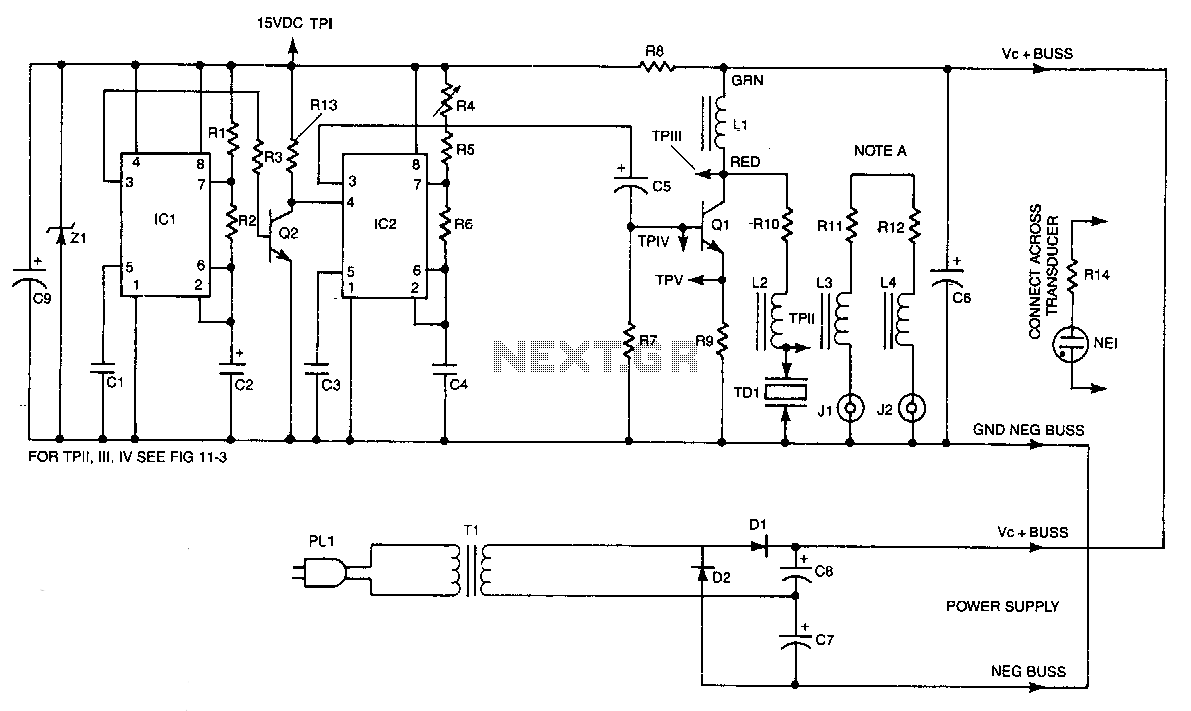
IC2 is a stable oscillator whose frequency and pulse width are determined by the values of R4, R5, R6, and C4. R4 is adjustable for precise frequency setting. The output from IC2 is at pin 3, which is capacitively...
Our present car controller runs on a single PIC16F870 micro and provides functions for remote door locks, headlight reminder, and car finder. It is constructed using wire-wrap to allow for future expansion and is mounted using Velcro on the...
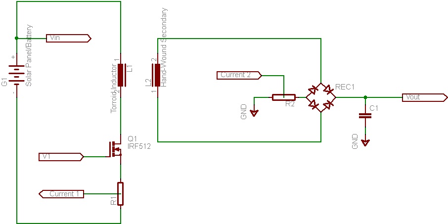
This document discusses the future direction of the Free Charge Controller project and proposes a new solar charge controller circuit. The Free Charge Controller project aims to enhance the efficiency and effectiveness of solar energy management systems. The proposed solar...