
UC3906 battery charger controller circuit

The UC3906 features separate voltage loop and current limit amplifiers that adjust the output voltage and current levels in the charger by controlling the onboard driver. The circuit requires a DC input voltage ranging from 18 to 22 volts. Three optical LED indicators display the charge state. The IC is configured to provide three charge states: Bulk charge, where the charger operates in a constant-current mode until the battery reaches the programmed full-charge voltage; Overcharge, where the charger switches to overcharge mode to ‘top-off’ the battery once the full-charge voltage is reached; and Float charge, which occurs when the current decreases to the minimum overcharge current, signaling the charger to enter float charge mode.
The UC3906 battery charger circuit is an efficient solution for managing the charging process of sealed lead-acid batteries. The integration of separate voltage and current control loops allows for precise regulation of the output parameters, ensuring optimal charging conditions. The necessity for a DC input voltage of 18 to 22 volts is critical, as it provides the required headroom for the charging process.
The three charge states are designed to accommodate the various stages of battery charging, enhancing battery longevity and performance. During the Bulk charge phase, the constant-current mode allows for rapid charging until the target voltage is achieved. Transitioning to the Overcharge state prevents the battery from becoming undercharged by providing a slight additional charge to ensure full capacity. Finally, the Float charge mode maintains the battery's charge without overloading it, which is crucial for long-term storage and usage.
The use of optical LED indicators not only enhances user interface but also provides real-time feedback on the charging status, allowing users to monitor the charging process easily. This comprehensive approach to battery management ensures that the UC3906 charger circuit can effectively extend the life of sealed lead-acid batteries while maintaining safety and efficiency throughout the charging cycle.This UC3906 battery charger circuit controller contains all of the necessary circuitry to control the charge and hold cycle for sealed lead-acid batteries. The UC3906 battery charger circuit is specifically designed to provide the proper charging voltage and current determined by the temperature and state of charge of the battery.
The UC3906 battery charger circuit controller monitor and control both the output voltage and current of the charger through three separate charge states . UC3906 has separate voltage loop and current limit amplifiers which regulate the output voltage and current levels in the charger by controlling the onboard driver.The charger circuit requires 18 to 22 volts DC input. Three optical ( LED ) indicators show the charge state . This IC is configured to provide three charge states: Bulk charge – the charger operates in a constant-current charge mode until the battery reaches the programmed full-charge voltage.
Overcharge – when the voltage reaches the programmed full-charge voltage, the charger switches to overcharge mode to ‘top-off’ the battery. Float charge – when the current decreases to the minimum overcharge current, the charger enters the float charge mode.
🔗 External reference
Related Circuits
This simple water detector circuit utilizes alternating voltage to prevent electrode corrosion. It is easy to construct and employs N1 as a trigger Schmitt gate to generate the AC signal. When a conductive substance, such as an aqueous solution,...
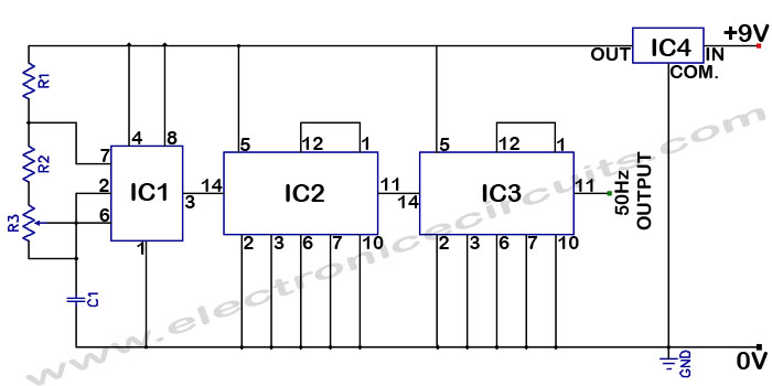
Accurate 50Hz Oscillator Circuit Using 555 and 7490. This circuit generates a 50Hz pulse. It consists of a 555 timer and two 7490 divide-by-ten counters. The circuit utilizes a 555 timer configured in astable mode to produce a square wave...
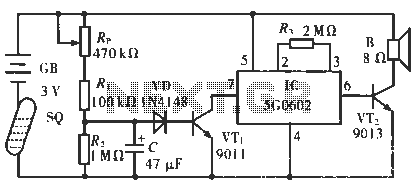
The circuit operates in such a way that when the patient is typically in an upright position, the SQ mercury switch is turned off, resulting in the alarm circuit being inactive. When the patient lies down, the SQ switch...
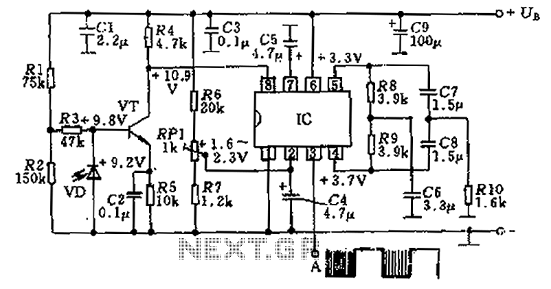
The circuit utilizes an integrated amplifier, resulting in a simple and compact design. The TDA4050 IC is employed, where a weak signal is received by the infrared photodiode (VD) and first passes through a transistor amplifier. The circuit is...
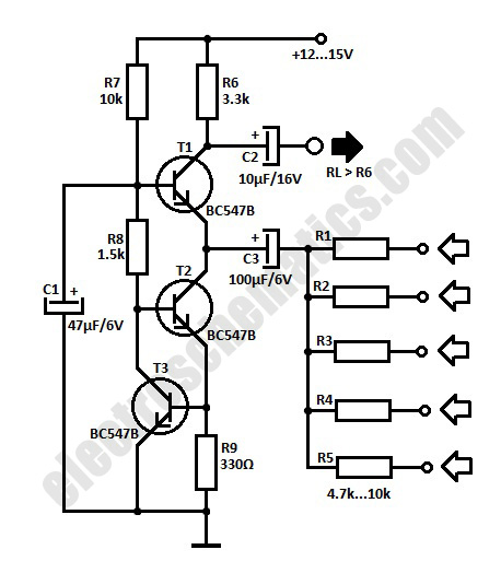
The simple audio mixer circuit is built on the common base principle, where input voltages are transformed into alternating currents which are summed to form the output. The simple audio mixer circuit utilizes a common base configuration to achieve effective...
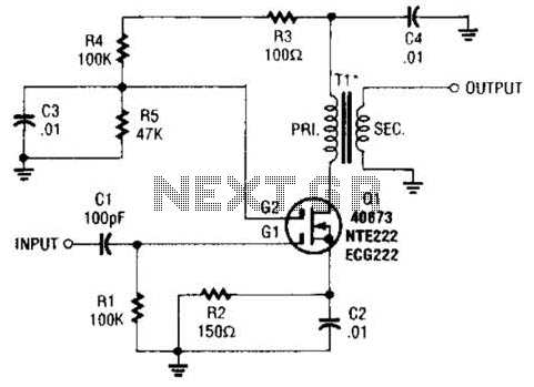
A MOSFET is utilized as a wideband buffer amplifier. T1 is wound on a toroid of approximately specified diameter, using material suitable for the frequency range, typically between 1 MHz and 20 MHz. The turns ratio should be approximately...