
Suitable comparator circuit headset detection

The circuit operates based on the principle of detecting the load impedance presented by the connected headphones or microphone. The RMIC-BIAS resistor plays a crucial role in establishing a stable reference voltage that is critical for accurate detection. When a headphone or microphone is connected, the change in load impedance alters the VDETECT voltage. The MAX9063 comparator is utilized for its precision in comparing the VDETECT against a set reference voltage, allowing for reliable identification of the connected device type. The comparator's design minimizes power consumption while maximizing performance, making it suitable for portable applications where battery life is a concern. The integration of hysteresis in the comparator enhances stability by preventing false triggering due to noise or voltage fluctuations. This is particularly important in mobile environments where the circuit may be subject to varying conditions. The overall design aims to provide an efficient and effective solution for headphone type detection in modern electronic devices.Headphone type detection circuit according to the figure attached. Figure, 2.2k RMIC-BIAS resistor connected to the audio controller provides a low noise reference voltage (VMIC-REF). When the audio jack is inserted, VMIC-REF voltage through RMIC-BIAS is applied to the plug - equivalent resistance (not shown) on the ground, so the MAX9063 in the noninverting input of a voltage VDETECT. For stereo headphones, the resistance is small (8, 16, or 32 ); for the microphone, the current source current because of the absorption of fixed types of different microphones in 100 A to about 800 A between floating and thus the resistance value is large.
Since VDETECT headphones into the jack with the type of change, it is possible to monitor VDETECT by a comparator to determine the type of headset. As shown, assume microcontroller reference voltage (VMIC-REF) is 3V, 32 headphone load produces VDETECT voltage of 43mV.
The fixed current 500 A microphone load, a voltage of 1.9V. Note that most applications will have problems VDETECT direct connection. Given the typical microcontroller port CMOS input logic level is higher than the requirements of 0.7 VCC and lower than 0.3 VCC, then 3.3V supply microcontroller input logic level should be higher than 2.3V, less than 1V. 1.9V level 500 A microphone load generated is not a valid logic "1" level. 100 A to 800 A microphone bias current will generate 2.78V to 1.24V for VDETECT, any voltage drops below 2.3V violates the controllers VIH (input high, assuming RBIAS to 2.2k ) requirements.
In order to obtain higher voltage or 2.3V, the microphone bias current must be 318 A or less. Otherwise we will have to change the 2.2k bias resistor, thereby changing the microphone detection threshold. Because of the typical load of 32 headphones can easily pull the level close to ground, thus generating a logic low of 1V or less easy to implement.
In order to detect the type of headset, you need to VDETECT connected to one input of the comparator, the reference voltage is connected to the other input. The comparator output, which represents the type of headset. This portable headset detect application should have a small size, and low power consumption. Shown comparator measuring just 1mm 1mm, maximum supply current of only 1 A. It has a strong mobile phone frequency anti-jamming capability, providing high reliability. The comparator also has internal hysteresis and low input bias current and other characteristics. These features make it to space, power consumption is extremely sensitive battery-powered products (such as: mobile phones, portable media players and laptops) an ideal choice for headset detection circuit.
Related Circuits
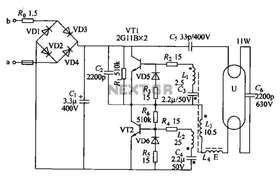
Energy-saving lamps are categorized into self-ballasted compact types and single-ended structures. They can also be classified based on appearance into various forms such as double-tube, four-tube, six-tube types, and others. The lifespan of energy-saving lamps is approximately ten times...
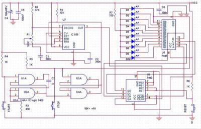
The speed test circuit is a simple design intended to measure a person's reaction time in a game. The operation of this peripheral is straightforward, facilitated by several integrated circuits, including a counter, timer IC, and decoder. The timer...
The following circuit illustrates the use of a 555 integrated circuit (IC) for an infrared (IR) remote control extender circuit. Features include support for 850 nm and 950 nm signal wavelengths, along with the capability to generate control pulses. The...
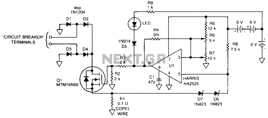
This 115 Vac electronic circuit breaker utilizes the low drive power, low on-resistance, and fast turn-off characteristics of the TMOS MTM15N50. The trip point is adjustable, and an LED fault indication is provided, with battery power ensuring complete circuit...
This project uses a 3909 IC and a few other parts; power is 1.5 volts DC. The project employs the 3909 integrated circuit (IC), which is a versatile component commonly used in various electronic applications, particularly in timer and oscillator...
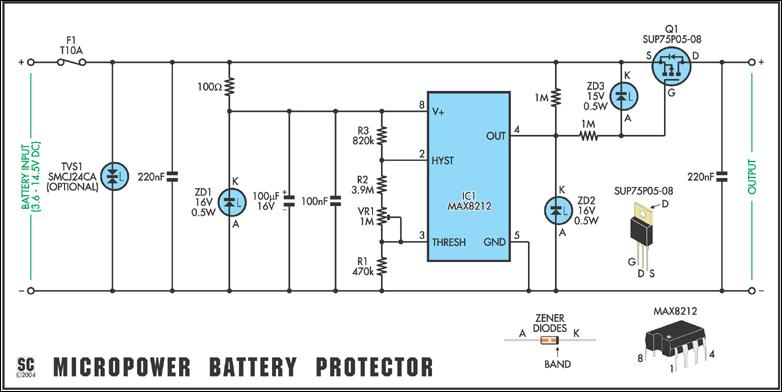
Protect expensive batteries from discharge damage with this mini-sized electronic cutout switch. It uses virtually no power and can be built to suit a wide range of battery voltages. The mini-sized electronic cutout switch serves as a crucial component in...