
HiJack car Alarm

This circuit implements a security mechanism aimed at preventing unauthorized vehicle operation in the event of a hijacking. The core functionality is triggered by the opening of a vehicle door while the ignition is active. The design includes a delay mechanism that allows the vehicle to operate for a brief period before the alarm activates, providing the hijacker time to distance themselves from the vehicle.
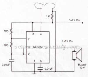
The circuit comprises several key components: a microcontroller or logic gate for processing the door switch input, a timing capacitor (C3) that determines the duration of the alarm delay, an LED indicator for visual feedback, and a buzzer for audio alerts. When the door is opened with the ignition on, the microcontroller detects this condition and initiates a countdown. After the predetermined delay, the alarm sounds, and the engine is disabled through a relay or electronic cut-off switch.
Safety considerations are critical in the implementation of this circuit. It is essential to ensure that the device does not inadvertently disable the vehicle under normal operating conditions. The choice of high-quality materials and components is necessary to maintain reliability and minimize the risk of failure, which could lead to dangerous situations.
The LED serves as a visual alert, illuminating when the alarm is triggered. The buzzer emits a short beep, the duration of which is controlled by capacitor C3, signaling the need for the user to reset the system. A reset button is included in the design, which, when pressed, will deactivate the alarm and extinguish the LED, allowing normal vehicle operation to resume.
Overall, this circuit provides a robust solution for vehicle security, but it requires careful consideration of both its installation and operational implications to ensure safety and compliance with legal standards.This circuit is designed primarily for the situation where a hijacker forces the driver from the vehicle. If a door is opened while the ignition is switched on, the circuit will trip. After a few minutes delay - when the thief is at a safe distance - the alarm will sound and the engine will fail.
Before fitting this or any other engine cut-out to your vehicle, carefully consider both the safety implications of its possible failure - and the legal consequences of installing a device that could cause an accident. If you decide to proceed, you will need to use the highest standards of materials and workmanship. You`re going to trip this alarm unintentionally. When you do, the LED will light and the Buzzer will give a short beep. Its length is determined by C3. Its purpose is to alert you to the need to push the reset button. When you push the button the LED 🔗 External reference
Related Circuits
This is a computer I built for my car, its an MP3 music system but can also do other tasks. Based around a super-small sub-micro ATX motherboard from a computer known as the BookPC BKi810, I have put the...
The circuit of a burglar alarm utilizing IC timer 555/556 functions as a security measure to prevent unauthorized entry into a premises. The alarm generates a loud sound when a thin wire connecting resistor R1 with pin 4 of...
This is the lowest cost dialing alarm on the market and shows what can be done with an 8-pin microcontroller. The complete circuit is shown below. You cannot see all the features of this project by looking at the...
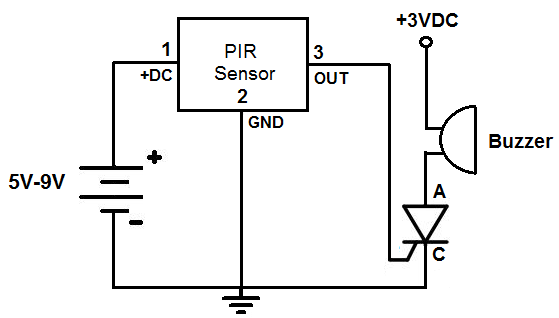
This is an alarm circuit that activates when motion is detected. Upon detection, the circuit triggers an alarm buzzer, which remains activated until the power is disconnected. This type of alarm circuit is commonly used to monitor areas for...
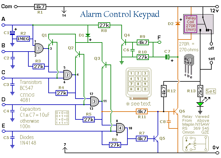
This keypad is designed for use with the Modular Burglar Alarm system, although it can be applied in various other contexts. Inputting the first four digits of a selected five-digit code will activate the relay, while entering the complete...
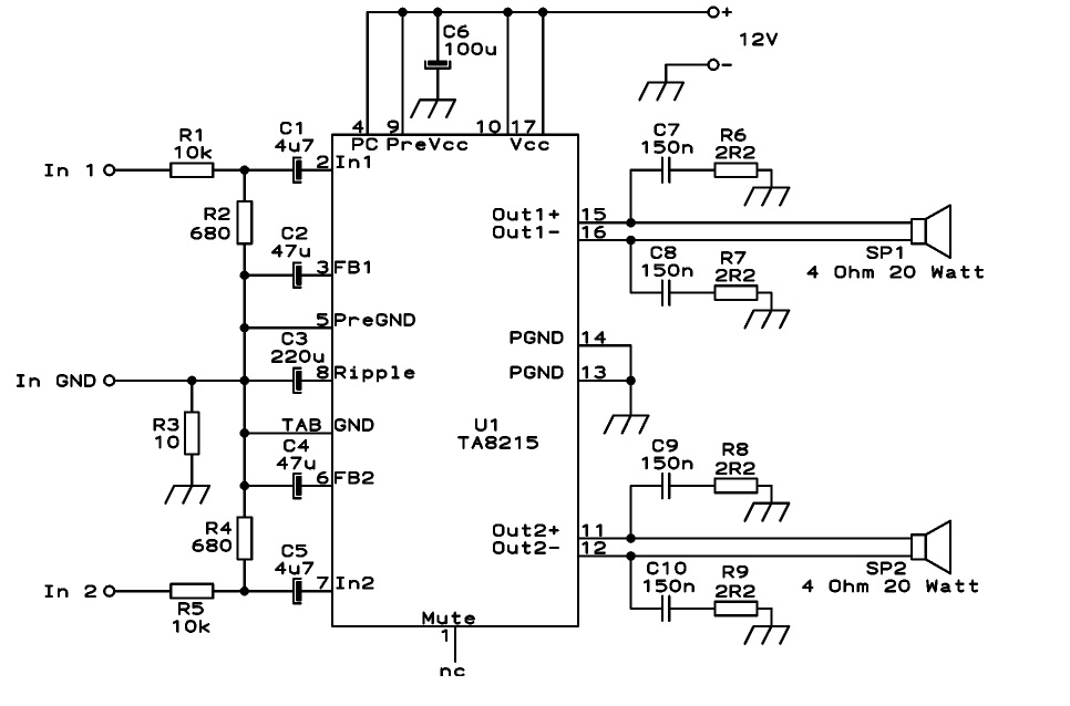
This circuit is designed as a stereo BTL (Bridge-Tied Load) 15W audio power amplifier using the TA8215 integrated circuit developed by Toshiba. Two TA8215 ICs are utilized in this configuration to achieve four output channels, with each IC providing...