
Switch mode power supply

The described buck converter circuit is designed to efficiently step down a higher DC voltage to a lower DC voltage while providing a stable output current. The input voltage range of 24 to 32 V DC is suitable for various applications where such voltage levels are common, such as in industrial power supplies or battery-powered systems.
The operation of the circuit is based on the principle of pulse-width modulation (PWM), where the PWM125 controller regulates the duty cycle of the two power MOSFETs. By alternating the conduction of these MOSFETs, the circuit minimizes power losses and improves overall efficiency. The switching frequency of 150 kHz is a typical choice for such applications, balancing efficiency and component size.
The output from the MOSFETs is first transformed to a lower voltage level, which is crucial for ensuring that the final output meets the desired specifications of 5 V DC at a maximum current of 8 A. The transformation process may involve the use of an inductor and possibly a transformer, depending on the specific design of the circuit.
After voltage transformation, the signal is rectified to provide a smooth DC output. The rectification process typically employs diodes or synchronous rectification techniques to further enhance efficiency and minimize voltage drop.
The efficiency metrics indicate that the circuit performs adequately at lower input voltages, achieving 75% efficiency between 22 to 32 V. However, this efficiency can rise to approximately 90% when the input voltage is increased, showcasing the design's capability to adapt to varying input conditions while maintaining performance.
This buck-derived circuit is ideal for applications requiring efficient power conversion with specific output voltage and current requirements, making it suitable for a wide range of electronic devices and systems.This buck-derived circuit provides up to 8 A at 5 Vdc operating off 24 to 32 Vdc. The two power MOSFETs in the circuit conduct alternately for equal periods. Switching frequency is 150 kHz, set by the PWM125 controller. Output of the two MOSFETs is transformed to a low-voltage level, then rectified. Efficiency of the circuit is 75% when operated in a 22 to 32 V range. Efficiency approaches 90% with higher voltage inputs.
Related Circuits
The 0 to 130-volt voltmeter and neon "AC PWR" lamp provide an average indication of AC power. The fuse and metal oxide varistor (MOV) protect the monitor against overvoltage spikes. Four 1N4004 diodes rectify the AC voltage, generating negative-going...
Many antique radios operate on batteries, including tube portables like the Zenith model K-401 and "farm" radios used in rural areas without electrical power. This article provides historical context on battery usage in early radios and offers guidance on...
This document presents a very low-power monolithic 1.9GHz silicon Low Noise Amplifier (LNA) that operates with a total current consumption of 1.75mA, which includes the bias circuit. The described Low Noise Amplifier (LNA) operates at a frequency of 1.9GHz, making...
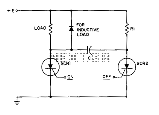
This circuit is a static SCR switch designed for use in a DC circuit. When a low-power signal is applied to the gate of SCR1, this SCR is triggered, allowing voltage to be applied to the load. The right...
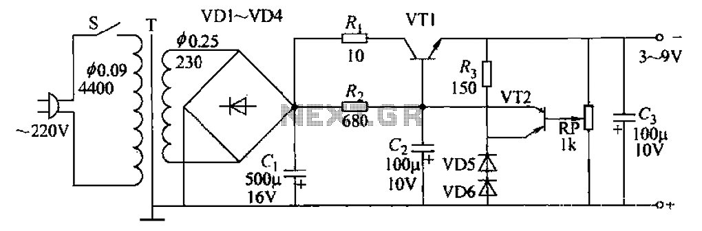
A 3-9V adjustable 100mA power supply is presented, featuring a series regulator circuit that utilizes amplifier tubes. The output voltage can be continuously adjusted between 3V and 9V, with a maximum output current of 100mA, making it suitable for...
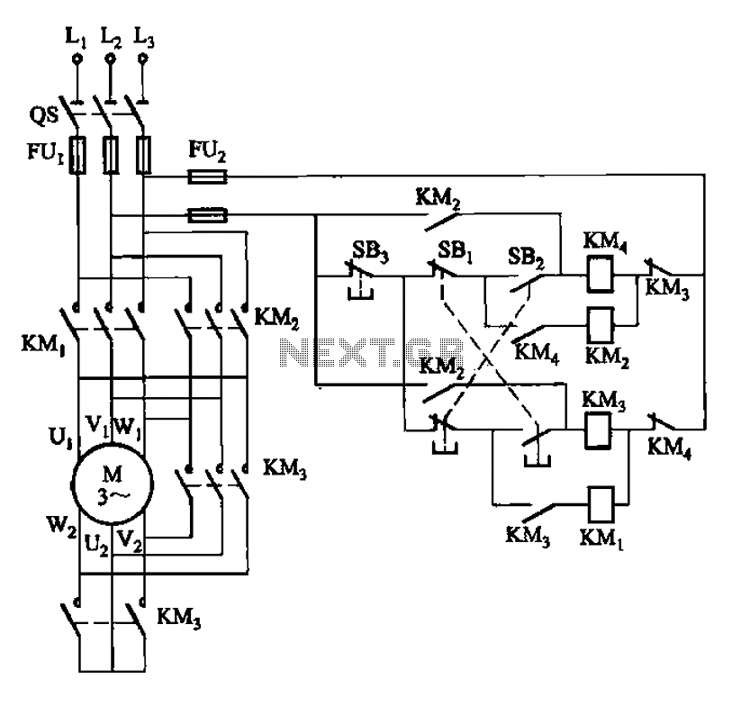
33 kW and above windlass with Y-conversion power-saving circuit The circuit design for a windlass rated at 33 kW and above incorporates a Y-conversion power-saving mechanism. This design is crucial for optimizing the efficiency of the windlass, which is commonly...