
Switching Power Supply

The circuit's design emphasizes the importance of efficiency in energy transfer and sound generation. By utilizing a stepper motor's dual-phase output, the circuit effectively captures even the slightest movements, converting them into electrical energy. The choice of the 551 oscillator enables high-frequency operation, which is critical for rapid switching of the TIP120 transistor. This transistor's role is pivotal, as it controls the inductor's current flow, allowing for effective energy storage in the magnetic field during the brief on-state and subsequent energy release to the capacitor during the off-state.
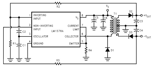
The dual-capacitor configuration not only maximizes energy storage but also minimizes losses due to internal resistance, which is crucial for maintaining high voltage levels. The design's ability to generate 50V demonstrates its capability for robust performance, particularly in applications requiring dynamic sound output. The integration of a regulated output for microcontroller operation reflects a forward-thinking approach, ensuring that the system can evolve and incorporate additional functionalities as needed. The exploration of a self-interrupting oscillator for low voltage applications indicates a commitment to advancing the technology for practical use in exertion instruments, aiming for enhanced performance and reliability in future iterations.The circuit in the schematic below is an improved piece of generator electronics. This is an unregulated switcher. Its function is to make the instrument as loud as possible while keeping the CPU running as long as possible. It transfers electrical energy from the generator more efficiently than rectifier and ACMultiplier circuits.
It is being imp roved on this website as a group activity. In this circuit, each of the two phases of the stepper motor gets doubled then summed. This is done so that the smallest body movements can generate sufficient voltage to make a sound, even if it`s very quiet. The difference between very loud sounds and very quiet sounds is usually important in music. It is termed the dynamics of the music. This circuit uses a 551 oscillator. The 551 is low-voltage version of the 555 Timer. It oscillates at about 200KHz and drives the base of a power transistor. The base of the power transistor is gated all-on, or all-off. This ensures that the transistor is operating in its most efficient region. This is typical of power-switching circuits such as regulators and type Damplifiers. In this circuit, a TIP120 transistor switches the generator`s current into the inductor for brief bursts (about 500 ns) and then disconnects the inductor for 4500ns.
500 ns is long enough to establish a magnetic field in the coil. In the 4500ns interval, the magnetic field in the coil induces a current in the wire which charges the capacitor. The voltage in the capacitor is nearly insignificant - when the coil`s current is released, it flows into the capacitor.
The only practical current limit arises from the internal impedances of the coil and the capacitor(s). In this circuit, the output capacitance is actually a parallel combination of two capacitors: One electrolytic and ceramic.
This is done for extra efficiency. The ceramic capacitor has a smaller internal resistance. This unregulated circuit has generated 50V unloaded with brief twists of the motor! To continue progress, a second regulated output (3V) will be added to power a microcontroller. In the future, the following self-interrupting oscillator will be evaluated for use in Exertion Instruments: Oscillator with Super Low Supply Voltage 🔗 External reference
Related Circuits
A 50W isolated forward-converter switching supply for telecom applications is described. Most aspects of the design are discussed. The 50W isolated forward-converter switching supply is engineered to meet the specific demands of telecom applications, where reliability and efficiency are paramount....
The interval between rings can be adjusted by changing the value of the 1 Meg resistor. A 70 volt, 30 Hz ringing voltage is generated from the 120 volt side of a small 12.6 VAC power transformer (Radio Shack...
This RS232 power supply circuit diagram is a simple RS-232 line driver power supply that operates from an input voltage as low as 4.2V and delivers an output of ±12V at ±40 mA with an efficiency of better than...
The supply voltage is 5V, and the goal is to increase it to 12V with a load current of 1A, resulting in an output power of 12W. A switching frequency of 20kHz has been selected, requiring a duty cycle...
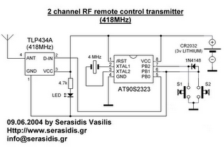
The following circuit illustrates a 3V power supply designed for an RF remote control circuit. This circuit is based on the AT90S2323 integrated circuit (IC). Features include a data rate of 2400 bps. The 3V power supply circuit for the...
A truly timeless circuit. The LM317 is a versatile and highly efficient 1.2-37V voltage regulator that can provide up to 1.5A of current with a large heat sink. It is ideal for just about any application. This was the...