
Switching two-speed motor control circuit

The motor switch control circuit is designed to facilitate the operation of a motor at two distinct speeds while enabling counter-steering functionality. This is particularly useful in applications where bidirectional control is required, such as in robotics or automated vehicles.
The circuit typically consists of a motor, a switch mechanism, and control logic to manage the speed settings. Two separate speed settings can be achieved through the use of a multi-position switch or a relay system. The switch connects the motor to different voltage levels or current paths, resulting in varying speeds.
For instance, in one configuration, activating the switch in one position may connect the motor to a higher voltage, allowing it to operate at full speed. Conversely, switching to another position may reduce the voltage, thereby decreasing the motor speed.
Counter-steering is achieved by reversing the polarity of the motor's supply voltage. This can be done using an H-bridge configuration, which enables the motor to rotate in either direction. The control logic may include microcontroller signals or simple transistor switching to manage the direction and speed of the motor effectively.
Safety features, such as current limiting resistors or thermal protection, can be integrated into the circuit to prevent damage from overcurrent situations. Additionally, feedback mechanisms, such as encoders or potentiometers, can be employed to provide real-time information on the motor's speed and position, enhancing the overall control strategy.
Overall, this motor switch control circuit is an essential component in systems requiring precise motor control with the capability to operate at multiple speeds and in both forward and reverse directions.Motor switch control circuit shown in Figure offers two speeds counter-steering i.e. two speeds in the opposite direction.
Related Circuits
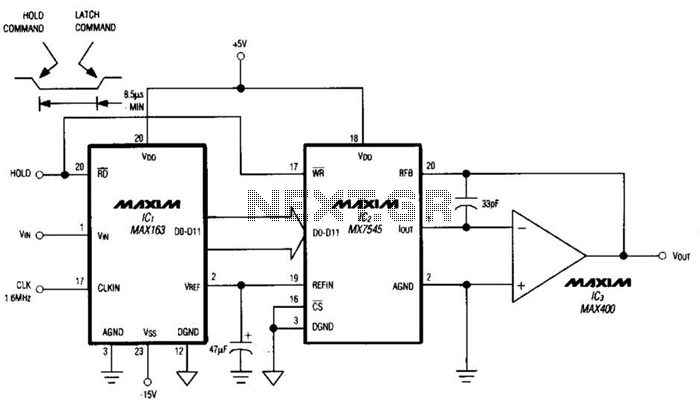
Driving a D/A converter using an A/D converter provides an overall analog-hold function. Although this function has limitations in output resolution, it offers zero voltage droop and infinite hold time. The A/D converter depicted (IC1) features a 12-bit compatible...
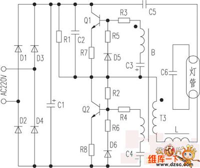
The saving lamp circuit features two main types: glass cover and exposed. The glass cover variants include three series: spherical, cylindrical, and processing types. The first two series consist of four variations: transparent, carved, engraved, and white. These lamps...
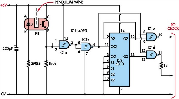
This document outlines the construction of a pendulum-controlled clock designed for high accuracy. Although it has a retro appeal, it represents an intriguing project. The project requires a spare quartz clock, which must be modified by isolating two pads...
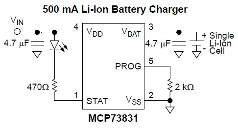
Nokia BL-4C and BL-5C are 3.7V, 700-1000mAh (various) lithium-ion batteries that have three terminals. These terminals include a positive terminal, a ground, and a BSI (Battery Status Indicator) terminal, which presents a fixed resistance value that needs to be...
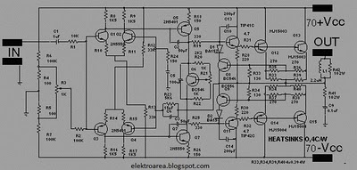
The design of this amplifier aims to enhance the reproduction of complex music and voice. While high electrical properties are emphasized, the primary objective is to achieve superior sound quality, vivid imaging, and exceptional spatial clarity. Although the average...
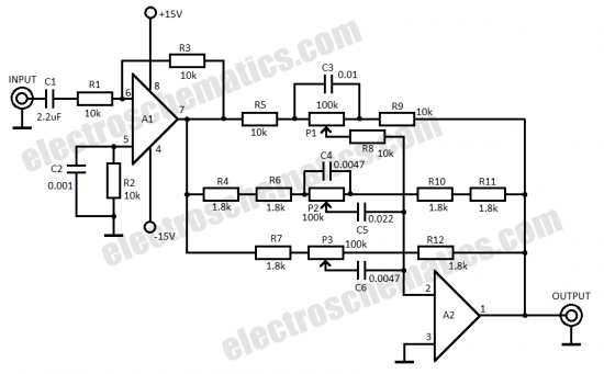
This three-band equalizer circuit functions as an active filter network for bass, mid, and high audio frequencies. It is built around the LM833 operational amplifier from National Semiconductors. The output of this three-way graphic equalizer is configured to be...