
Sample-And-Hold Circuit Ii Circuit

The described circuit utilizes an A/D converter (IC1) that incorporates a 12-bit track/hold mechanism, which is crucial for maintaining signal integrity during the sampling process. The track/hold function allows the circuit to capture the analog signal at a specific moment in time, holding that value steady while the D/A converter processes it. This is particularly important in applications requiring precise signal reconstruction, as it minimizes the effects of voltage droop that can occur during the conversion process.
The specifications of the A/D converter indicate a full-power bandwidth of 6 MHz, meaning it can accurately sample signals up to this frequency without significant distortion. The 30 ns aperture delay specifies the time it takes for the track/hold circuit to switch from tracking to holding mode, while the 50 ps aperture jitter indicates the stability of the sampling moment, which is essential for high-resolution applications.
The D/A converter is directly connected to the A/D converter, allowing it to reconstruct output signal levels that fall within the specified range of 0 to 5 V. This connection ensures that the digital representation of the analog input is accurately translated back into an analog signal, facilitating various applications such as audio processing, signal conditioning, and control systems. The combination of these components provides a robust solution for analog signal processing, ensuring high fidelity and stability in the output signal. Driving a D/A converter with an A/D converter provides an overall analog-hold function, which though limited in output resolution, offers zero voltage droop and infinite hold time. The A/D converter shown (IC1) includes a 12-bit compatible track/hold at its input. The track/hold specifies a 6-MHz full-power bandwidth, a 30-ns aperture delay, and a 50-ps aperture jitter.
The direct connections shown allow the D/A converter to reconstruct signal levels within the input range of 0 to 5 V.
Related Circuits
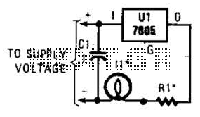
A 7805 can be configured as a constant-current regulator to function as an inrush current limiter. Resistor R1 will maintain a voltage of 5 V across it at all times, resulting in a total current through R1 of 5...
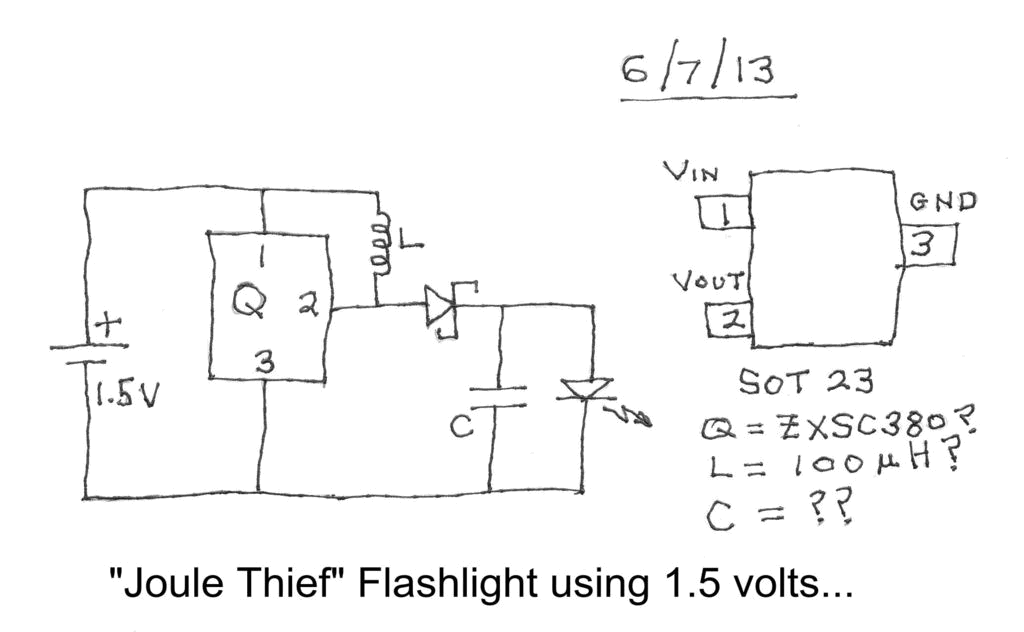
Investigating a Paradox: Recently, an energy-saving LED flashlight was observed for sale that utilized only one 1.5-volt battery. Upon purchasing this light and disassembling it, the expectation was to find a battery, bulb, switch, and a circuit board designed...
The following circuit illustrates a Boost Converter Circuit Diagram. This circuit is based on the 555 IC. Features: it only requires off-the-shelf components. The Boost Converter is a type of DC-DC converter that steps up the input voltage to a...

This is a simple basic design of a servo motor controller with a pulse generator. It utilizes the CMOS IC 7555 in astable mode to generate pulses for driving the motor. The servo motor controller circuit employs the CMOS IC...
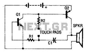
The circuit employs a two-transistor direct-coupled oscillator, with its frequency determined by capacitor C1, resistor R2, and the skin resistance across the touch pads. Since C1 and R2 are fixed values, only the skin resistance can vary the sound...
Control the state (on/off) and direction of two linear actuators that are essentially DC motors. The linear actuators operate at 12VDC and draw 10 amps of current at full load. A 25A external power supply has been purchased, as...