
Switchless NiCd-NiMH Battery Charger

This circuit serves as an improved solution for current limiting in battery chargers, particularly those designed for low-cost applications. Traditional battery chargers typically employ a single resistor for current limitation, which can lead to inefficiencies and heat generation. The proposed circuit enhances this design by incorporating additional components that optimize performance and reliability.
The schematic may include a combination of transistors, diodes, and operational amplifiers to create a more sophisticated current regulation mechanism. For instance, a transistor can be configured in a feedback loop to monitor the output current. When the current exceeds the preset limit, the feedback mechanism adjusts the base current of the transistor, thereby reducing the voltage drop across the load and maintaining the desired current level.
Additionally, the use of diodes can protect the circuit from reverse polarity and over-voltage conditions, further enhancing the safety and longevity of the charger. Operational amplifiers can be employed to provide precise voltage and current sensing, allowing for more accurate regulation and improved performance under varying load conditions.
Overall, this alternative circuit design not only replaces the traditional current limiting resistor but also provides a more efficient and reliable method for battery charging applications. By offering better thermal management and improved current regulation, it addresses the shortcomings of conventional designs, making it suitable for a wider range of battery types and charging scenarios.This circuit may be used to replace the single current limiting resistor often found in dirt cheap battery chargers. The alternative shown here will event.. 🔗 External reference
Related Circuits
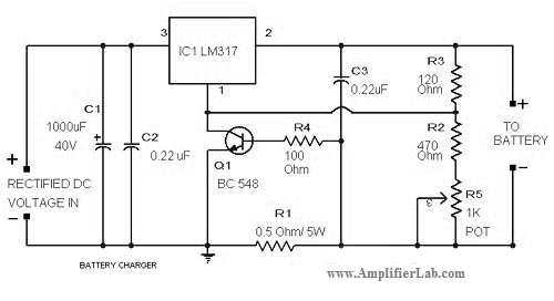
The circuit diagram of a lead-acid battery charger is presented here. The main component of this circuit is the IC LM317. The lead-acid battery charger circuit utilizing the LM317 voltage regulator is designed to efficiently charge lead-acid batteries while providing...
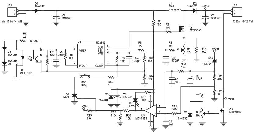
The Ultra Fast Battery Charger for Nickel-Cadmium (NiCad) battery cells is designed to efficiently charge NiCad batteries. This charger, referred to as the Ultra Fast NiCad Battery Charger, is capable of rapidly filling NiCad battery cells. The charger is...
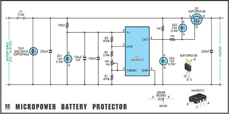
Protect expensive batteries from discharge damage with this mini-sized electronic cutout switch. It uses virtually no power and can be built to suit a wide range of battery voltages. The mini-sized electronic cutout switch serves as a crucial component in...
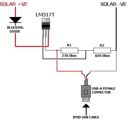
A solar charger for an iPod is no more difficult than creating a solar battery charger. Built-in iPod batteries operate at 3.7 Volts, with capacity (measured in mAh) varying by iPod model—e.g., 1,200mAh for a 2nd Gen, 850mAh for...
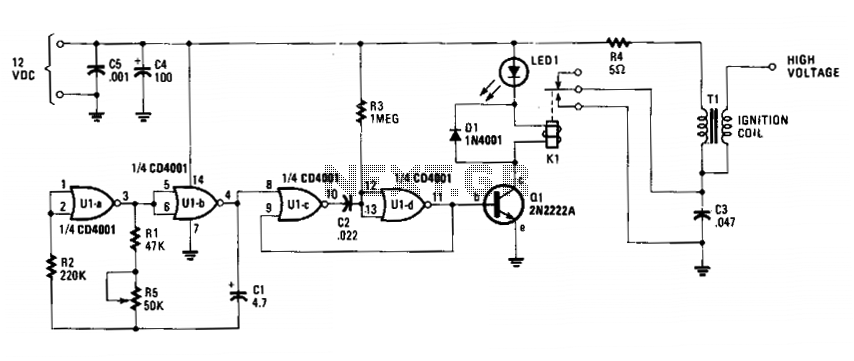
The circuit is fundamentally an auto ignition coil paired with a set of points that perform a similar function. It employs a pulsing circuit constructed from a single CMOS NOR integrated circuit (U1) to open and close relay contacts,...
This simple battery charger circuit is designed for NiMH/NiCd batteries. It requires no microcontroller or any programming. Linear Technology Corporation. The described battery charger circuit is intended for use with nickel-metal hydride (NiMH) and nickel-cadmium (NiCd) batteries, which are commonly...