
Simple Lead-Acid Battery Charger Circuit

The lead-acid battery charger circuit utilizing the LM317 voltage regulator is designed to efficiently charge lead-acid batteries while providing adjustable output voltage and current regulation. The LM317 is a popular adjustable three-terminal voltage regulator that can output a voltage range from 1.25V to 37V, making it suitable for charging various types of lead-acid batteries.
In this circuit, the input voltage is typically higher than the desired output voltage, often sourced from an AC to DC converter or a rectified power supply. The LM317 requires a minimum input-to-output voltage differential to function effectively, which is generally around 3V. Thus, if charging a 12V battery, the input voltage should be at least 15V.
The configuration of the LM317 in this application involves two resistors, R1 and R2, which set the output voltage according to the formula: Vout = Vref (1 + R2/R1) + Iadj * R2. Here, Vref is approximately 1.25V. By selecting appropriate resistor values, the output voltage can be tailored to match the nominal voltage of the battery being charged.
To ensure safe charging, a current limiting feature is often integrated into the circuit. This can be accomplished by including a sense resistor in series with the load, which allows the circuit to monitor the charging current. If the current exceeds a predetermined threshold, the LM317 will reduce the output voltage, thus preventing overcharging and extending the lifespan of the battery.
Additionally, it is advisable to include a heat sink on the LM317, as it may dissipate significant heat during operation, especially when charging at higher currents. Capacitors are also recommended at the input and output of the LM317 to stabilize the voltage and filter out any noise.
Overall, the lead-acid battery charger circuit using the LM317 is a versatile and effective solution for charging batteries safely and efficiently, with adjustable output parameters to accommodate various battery specifications.The circuit diagram of lead acid battery charger has been described here. The core part of this circuit is the IC LM 317. 🔗 External reference
Related Circuits
ETl3X220 is a cost-effective single-chip transmitter that operates via RF communication. It supports up to 10 channels and is ideal for applications such as wireless mice, keyboards, and other communication devices. The main technical features include: - Analog FM...
A larger version of the circuit diagram can be accessed by clicking here. The circuit was created using Eagle from CadSoft, which is a free schematic and PCB layout software for small non-commercial projects. The core component of the...
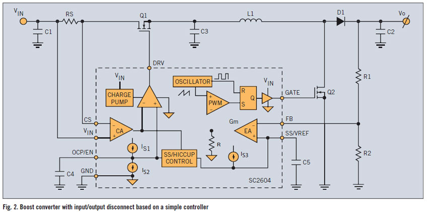
A PWM boost converter in a simple controller has a DC path from input VIN to VOUT, which is utilized for high-efficiency power conversion. A PWM (Pulse Width Modulation) boost converter is an essential component in power electronics, designed to...
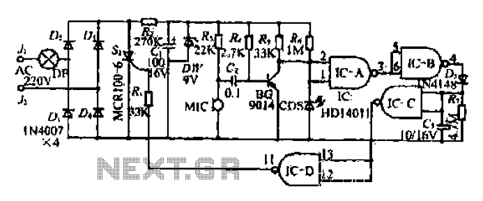
The circuit operates at 380V for air flow. Power is supplied through a step-down transformer, which rectifies the output to 9V DC. When the pump operates correctly, a button labeled 'S' is activated. The circuit utilizes a TWH8778 component....
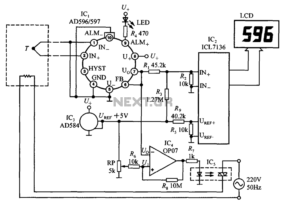
The circuit using AD596/597 forms a temperature measurement and control instrument. In this setup, AD596/597 (IC1) functions as a closed-loop thermocouple signal conditioner. IC2 is a monolithic CMOS 3 1/2 bit A/D converter ICL7136, which can also replace ICL7106,...
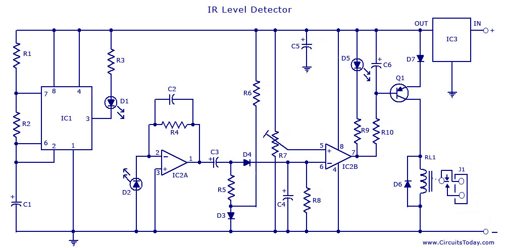
An infrared (IR) sensor or detector circuit diagram utilizing a 555 integrated circuit (IC), primarily employed as a water level or liquid level sensor and proximity detector circuit. The described circuit employs a 555 timer IC configured in a monostable...