
synced using infrared phototransistors

When a train disrupts the infrared beam, the phototransistor conducts less current, causing the voltage at the MINUS input of the comparator to exceed the reference voltage at the PLUS input, as determined by resistors R3 and R4. This results in the comparator output turning ON, which activates the LED. Proper alignment of the emitter and detector is crucial for optimal operation, particularly over larger gaps. Alignment can be facilitated using a string stretched between the LED and phototransistor or employing a length of dowel or stiff wire. For extended distances, a laser pointer can be directed through one of the mounting holes for alignment. The ideal beam height should match the coupler height and be angled across the tracks. The emitter may also be positioned above the track, with the phototransistor situated between the rails, particularly in concealed areas such as hidden yards. Angling the emitter and detector can further enhance performance.
The circuit design incorporates several key components and considerations for effective infrared detection in model railroading applications. The use of the LM339 quad comparator allows for precise voltage comparisons, enabling reliable detection of interruptions in the infrared beam. The choice of infrared emitter and detector pairs is critical, as their matching characteristics will significantly influence the sensitivity and range of the detection system.
The configuration of the resistors, particularly R1, R3, and R4, must be carefully selected to achieve the desired sensitivity and response time. R1's adjustment allows for calibration based on the specific environment and distance between the emitter and detector. The physical arrangement of components is also paramount; ensuring that the infrared beam is unobstructed and properly aligned maximizes detection efficiency.
In practical applications, testing and iterative adjustments may be necessary to fine-tune the system for optimal performance. The integration of sound output in response to beam interruption adds an interactive element, enhancing user engagement with the maze and detection system. Overall, this circuit exemplifies a robust approach to infrared detection in model railroading, combining effective component selection, careful alignment, and adaptability to various scenarios.Below is the circuit I`m working with; I plan on having the infrared phototransistor pairs inserted in 3 locations in the middle of the maze, including the end point. The width of the maze will be small enough for one finger to be able to slide in it, and as both fingers pass the phototransistors, they will cause a sound to be emitted from the spe
aker. This page presents information on infrared Across The Track` train detection circuits. The circuits are designed around the LM339 quad comparator chip and can use a wide assortment of matched infrared emitter / detector pairs. There is also a method that can be used for longer range across track detection that could be used for yard throats.
A detector circuit of this type is in use at the London Model Railroad Group`s club layout and spans seven O Scale tracks using one infrared LED and a lensed phototransistor. In the circuit bellow the LED will turn on when the infrared beam is broken. The value of the resistor R1 determines the sensitivity of the phototransistor Q1. In most cases a value of 1 Meg or 470K ohm with good results but every situation is different and some experimentation might be needed.
Circuit Operation When a train breaks the infrared beam the phototransistor will conduct less current. The voltage at the MINUS input of the comparator will rise above the reference voltage at the PLUS as determined by R3 and R4.
The output of the comparator to turn ON and the LED will be lit. Good alignment of the emitter and detector is important for good operation, especially if the gap is large. This can be done with a piece of string stretched between and in line with LED and phototransistor. A length of dowel or stiff wire could be used to set the alignment. Another method that can be used for longer distances is a laser pointer shone through one of the mounting holes.
The next diagram shows two methods of aligning the emitter and detector mountings. For best results the height of the beam should be at coupler height and at an angle across the tracks. The emitter could also be mounted above the track with the phototransistor placed between the rails in locations such as hidden yards.
Placing the emitter and detector at an angle would again be helpful. 🔗 External reference
Related Circuits
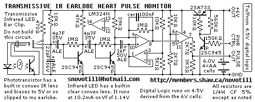
Senses heart pulse by means of an infrared earlobe clip. Reverse engineered circuit diagram of heart pulse sensor circuit board out of a treadmill. Notice that the output is level shifted for use by CMOS logic running on 4.5V...
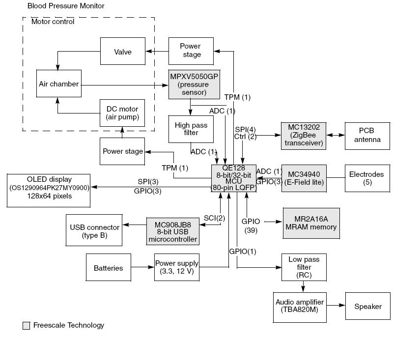
This article demonstrates the implementation of a system capable of measuring arterial blood pressure values. The arterial blood pressure measurement system typically consists of several key components, including sensors, signal processing units, and display interfaces. The primary sensor used in...

In this project AT89S52 microcontroller is used for interfacing to various hardware peripherals. The current design is an embedded application, which will continuously monitor a moving Vehicle and report the status of the Vehicle on demand. For doing so...
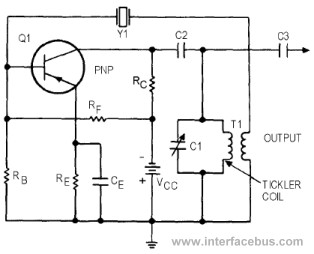
This circuit represents a variant of an Armstrong Oscillator. This specific example incorporates a crystal along with the LC tank circuit utilized in the previous Series-Fed Armstrong Oscillator. By definition, the Armstrong Oscillator employs a tickler coil for feedback...
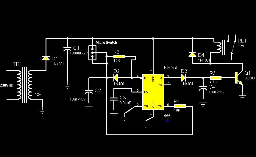
The circuit diagram illustrates a rotation sensor that activates a device, such as a motor or buzzer, when the circuit assembly is rotated. The design is based on the fundamental operation of a 555 timer. The rotation sensor circuit utilizes...
A pulse width modulator generates a PWM signal, which consists of pulses with a constant frequency while the duty cycle varies according to a modulating signal. A pulse width modulator (PWM) is an essential component in various electronic applications, particularly...