
Rotation Sensor Circuit Using 555 PCB

The rotation sensor circuit utilizes a 555 timer in monostable or astable mode, depending on the desired functionality. In monostable mode, the circuit generates a single output pulse when triggered by the rotation. This pulse can be used to activate a relay or transistor, which in turn powers the connected device, such as a motor or buzzer. The duration of the output pulse is determined by the resistor and capacitor values connected to the 555 timer.
In astable mode, the circuit continuously oscillates, producing a square wave output that can be used to drive the connected device in a more dynamic manner. The frequency of this oscillation is also determined by the resistor and capacitor values, allowing for customization based on the application's requirements.
The rotation sensor may incorporate additional components, such as potentiometers for adjusting sensitivity or diodes for protecting against reverse polarity. Proper placement of the rotation sensor and careful calibration of the timing components are crucial for ensuring reliable operation. The circuit can be powered by a standard DC supply, and the output can easily interface with various devices, making it suitable for a wide range of applications in automation and control systems.Circuit The picture shows the circuit diagram of a rotation sensor that can turn on a device like motor or buzzer while the circuit assembly rotates. The circuit is based on basic 555 timer operation. 🔗 External reference
Related Circuits
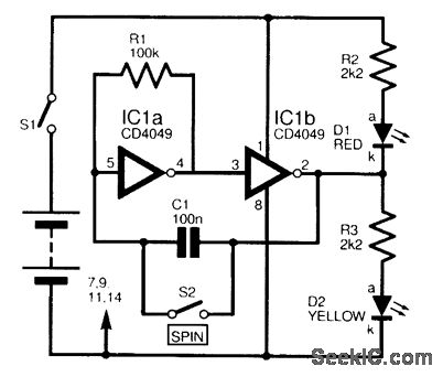
This circuit is designed to electronically simulate the tossing of a coin using a 4049 hex inverter integrated circuit (IC). It employs two of these ICs, specifically IC1a and IC1b, which are configured as an astable oscillator. This configuration...

The circuit diagram illustrates the application of a 915MHz RF2155 power amplifier. The radio frequency (RF) signal enters through pin 7, where it is processed by a preamplifier. The output from the preamplifier is further amplified by the power...
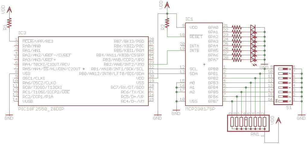
I2C are widely use for to communicate with external peripheral such as port expender, EEPROM, Real Time Clock etc. The Master Synchronous Serial Port (MSSP) module in PIC18 can be used to communicated with I2C peripheral. MSSP module can...
A distortion circuit is being developed utilizing a single 12AU7 tube configured as a diode. The design is acknowledged as basic, intended primarily for the purpose of adding distortion effects. The proposed circuit leverages the 12AU7 vacuum tube, which is...
The completed board may be driven by voltages between 0.8 and 3 Volts. While the basic design goal was candle-like light from a single cell, the values used were chosen to allow safe operation from 3 Volts so you...
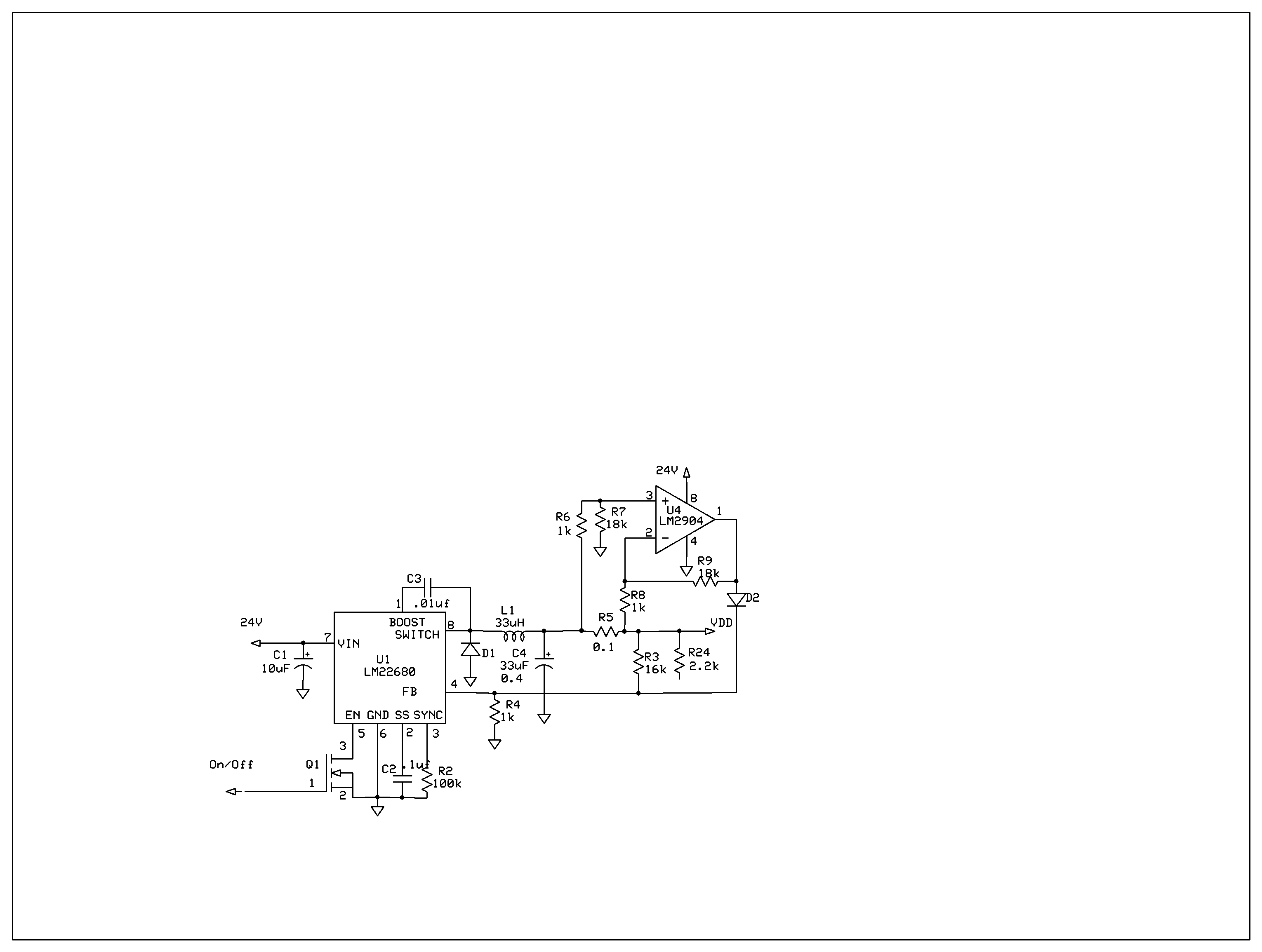
The product requires a voltage-controlled, current-limited power supply. Various switcher chips have been used with an op-amp to provide feedback for a current sense voltage to the feedback pin. Currently, an LM22680 is in use, but it has shown...