
Synchronous System

The circuit is designed to provide precise measurements of low resistances while minimizing the impact on the system under test. The use of a synchronous detection scheme is critical in this application, as it enables the circuit to reject common-mode noise and interference, which are prevalent in low-level measurements.
The 10-V peak, 1-kHz carrier signal generated serves as a reference for the synchronous detection process. By injecting a controlled 1-mA reference current into the unknown resistor, the circuit ensures that the voltage drop across the resistor can be accurately measured without introducing significant error or disturbance.
The amplification stage, consisting of instrument amplifier IC1 and precision op amp IC2A, is crucial for enhancing the small voltage signal generated across the resistor. With a gain of 100,000, this stage significantly boosts the signal, making it suitable for further processing. The choice of operational amplifiers is essential, as they must possess low noise characteristics and high input impedance to avoid loading the circuit under test.
The synchronous detector IC3 plays a vital role in demodulating the amplified voltage signal. This component extracts the desired DC component from the AC signal, effectively isolating the information related to the resistance measurement. Following this, operational amplifier IC2B acts as a low-pass filter, which is designed to suppress high-frequency noise and other unwanted signal components. By allowing only the DC voltage, which is directly proportional to the resistance, to pass through, the filtering stage enhances the accuracy and reliability of the measurement.
Overall, this circuit design exemplifies a sophisticated approach to low-resistance measurement, combining advanced signal processing techniques with careful component selection to achieve high precision while minimizing the influence of external factors. The circuit uses a synchronous-detection scheme to measure low-level resistances. Other low-resis-tance-measuring circui ts sometimes inject unacceptable large currents into the system-under-test. This circuit synchronously demodulates the voltage drop across the system-under-test and can hence use* extremely low currents while measuring resistance. The 10-V (pk), 1-kHz carrier generator injects a 1-mA reference current into unknown resistor, iTEST.
Instrument amplifier IC1 and precision op amp IC2A amplify the voltage across iTEST by a gain of 100 000. Synchronous detector IC3 demodulates this voltage, then op amp IC2B acts a low-pass filter on the demodulated voltage.
The low-pass filtering will attenuate all uncorrected disturbances (such as noise, drift, or offsets), while passing a dc voltage that is proportional to the unknown resistance.
Related Circuits
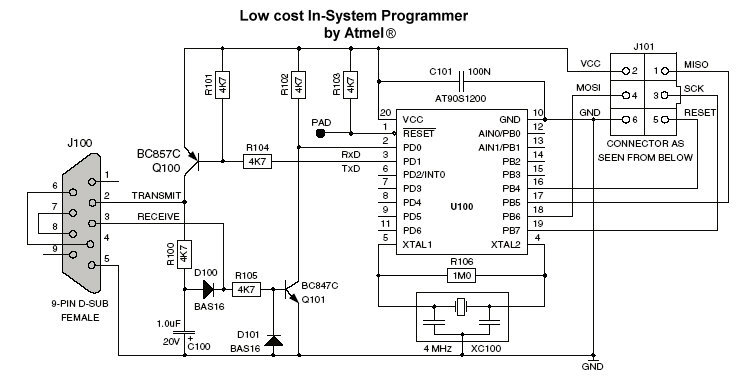
A programmer is available in the "AVR Software and Technical Library - April 2003" CD-ROM and has been published due to its stability and compatibility with AVR Studio 4. It has been tested with the AT90S2313 microcontroller and functioned...
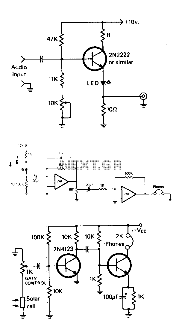
The simple modulator stage will accommodate most common LEDs. By adjusting the potentiometer, the bias of the transistor is varied until the LED is at its half output point. Then, audio will cause it to vary above and below...
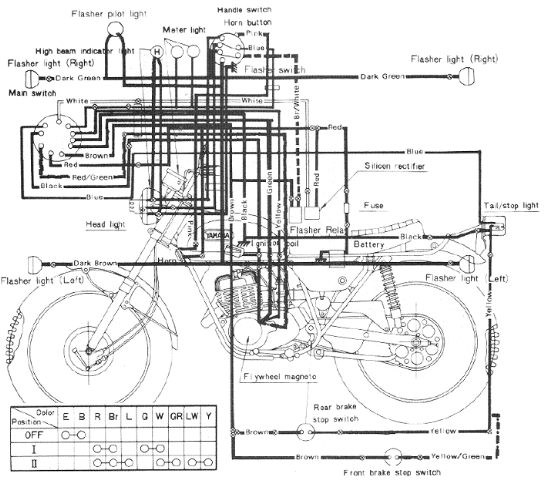
The following image illustrates the Yamaha 175 Wiring Diagram (CT2 and CT3 model) and Electrical System Schematic. It provides detailed information regarding the interconnection and wiring between electrical components of the motorcycle, including the battery, ground, headlight, taillight, horn,...
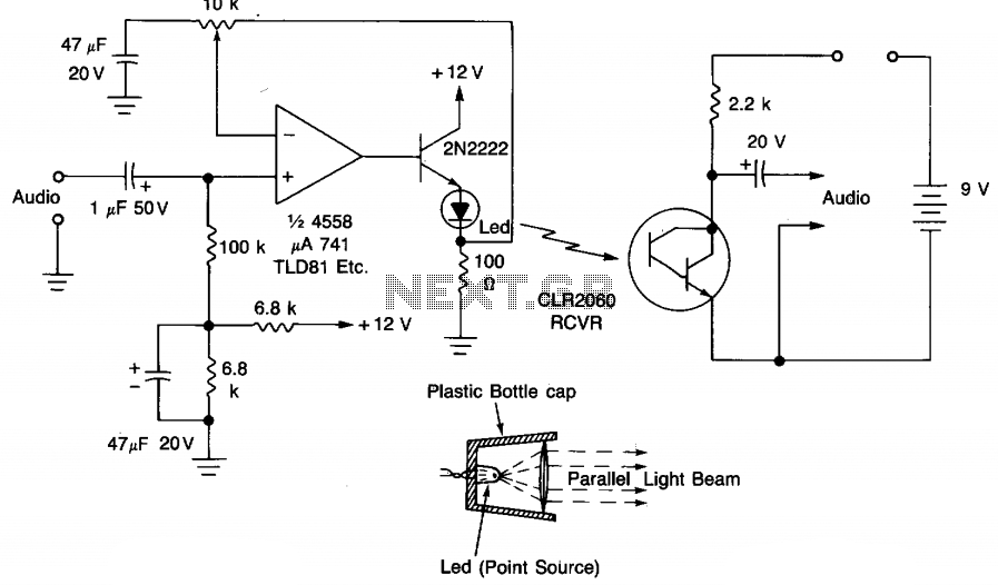
The circuit modulates the light emitted by an LED using either a crystal microphone or a loudspeaker output. To achieve maximum range, the optical system must operate efficiently. A convex lens or a concave mirror can be utilized to...
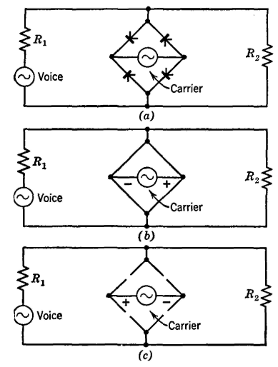
The Type C system was first installed around 1925 and has been extensively utilized since then. It incorporates the most desirable features of previously considered systems. Similar to the Type A system, the carrier signal is suppressed, minimizing the...
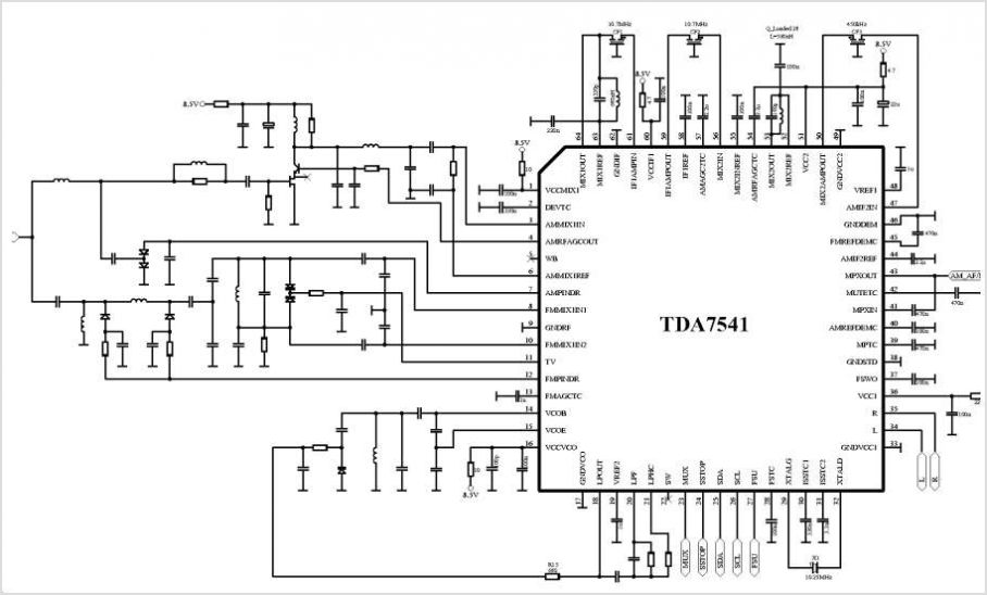
The TDA8340Q and TDA8341Q are integrated intermediate frequency (IF) amplifier and demodulator circuits designed for color and black-and-white television receivers. The TDA8340Q is intended for use with NPN tuners, while the TDA8341Q is suitable for PNP tuners. Both components...