
synth tr909
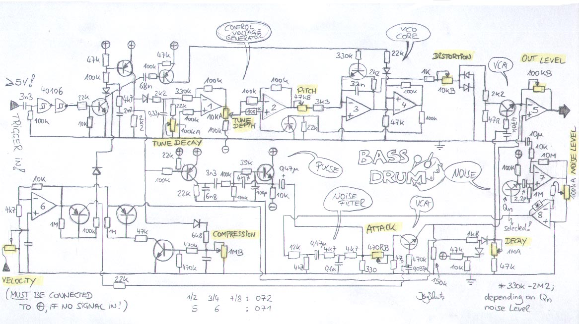
The PCB design for the modified TR909 bass drum circuit incorporates several key features that enhance its functionality and usability. The primary innovation is the addition of a compression potentiometer, which allows for greater control over the envelope shaping of the audio signal. This feature provides users with the ability to customize the dynamic response of the bass drum sound, making it more versatile for different musical styles.
Furthermore, the inclusion of an adjustable noise circuit expands the sonic palette available to the user. Unlike the original TR909, where noise levels are fixed, this design permits users to fine-tune the noise from 0% to maximum. This flexibility is particularly advantageous for sound designers seeking to create unique drum sounds or to blend noise with the primary bass drum signal for a richer texture.
The PCB layout is meticulously organized to facilitate easy assembly and maintenance. The component side view in the provided PDF allows for clear visibility of the placement of each component, ensuring that builders can accurately follow the schematic. The division of component placement into categories—pots, resistors, and other components—further aids in the assembly process, minimizing the potential for errors.
Transistor identification is straightforward, with clear markings indicating the specific types used in the circuit. The BC559 and BC549 transistors are commonly used in audio applications for their reliable performance. The choice of 1% metal film resistors throughout the design ensures precision in resistance values, contributing to overall circuit stability and sound quality.
This comprehensive approach to both the design and documentation of the PCB enhances the user experience, making it accessible for both novice and experienced builders while maintaining the high-quality standards associated with electronic musical instruments.This PCB was inspired by Colin Fraser, who found some very useful extensions to the bass drum circuit of the Roland TR909. Trevor page`s 9090 - project was of course also very helpful for me ! As an addition to these modifications, I added a "compression" pot, changing the behaviour of the envelope of the tri/sine signal a bit, see schematics for
detail. As it is a standalone bass drum, I added the noise circuit on the board. Noise is adjustable from 0% to maximum, unlike in the original TR909. Here you will find a PDF-file, containing the PCB of the tr909 bass drum circuit (component side view !) and 3 pics for component placement : I divided these into : Pots, Resistors and all the other things (for a better view). The transistors are depicted as they are built into the PCB, "5" means BC559, "4" means BC549. All Diodes are 2N4148. In my projets I allwys use 1% metal film resistors. 🔗 External reference
Related Circuits
Originally I intended to have 32 faders. Once I tried fitting them on a veroboard, 32 seemed rather excessive so I have reduced to sixteen. This still allows generation of accurate eighth harmonic which compares well with the Hammond's...
The MC145152-2 synthesizer can be programmed using DIP switches, a diode matrix, or EPROM look-up tables. However, it is now difficult to find, costing around US$30. Modern synthesizers require PIC processors for programming or must remain connected to a...
This document outlines the design of a low-cost 90 W flyback switching power supply intended for use in a multi-sync color monitor. To reduce screen interference caused by switching noise, the power supply can be automatically synchronized to the...
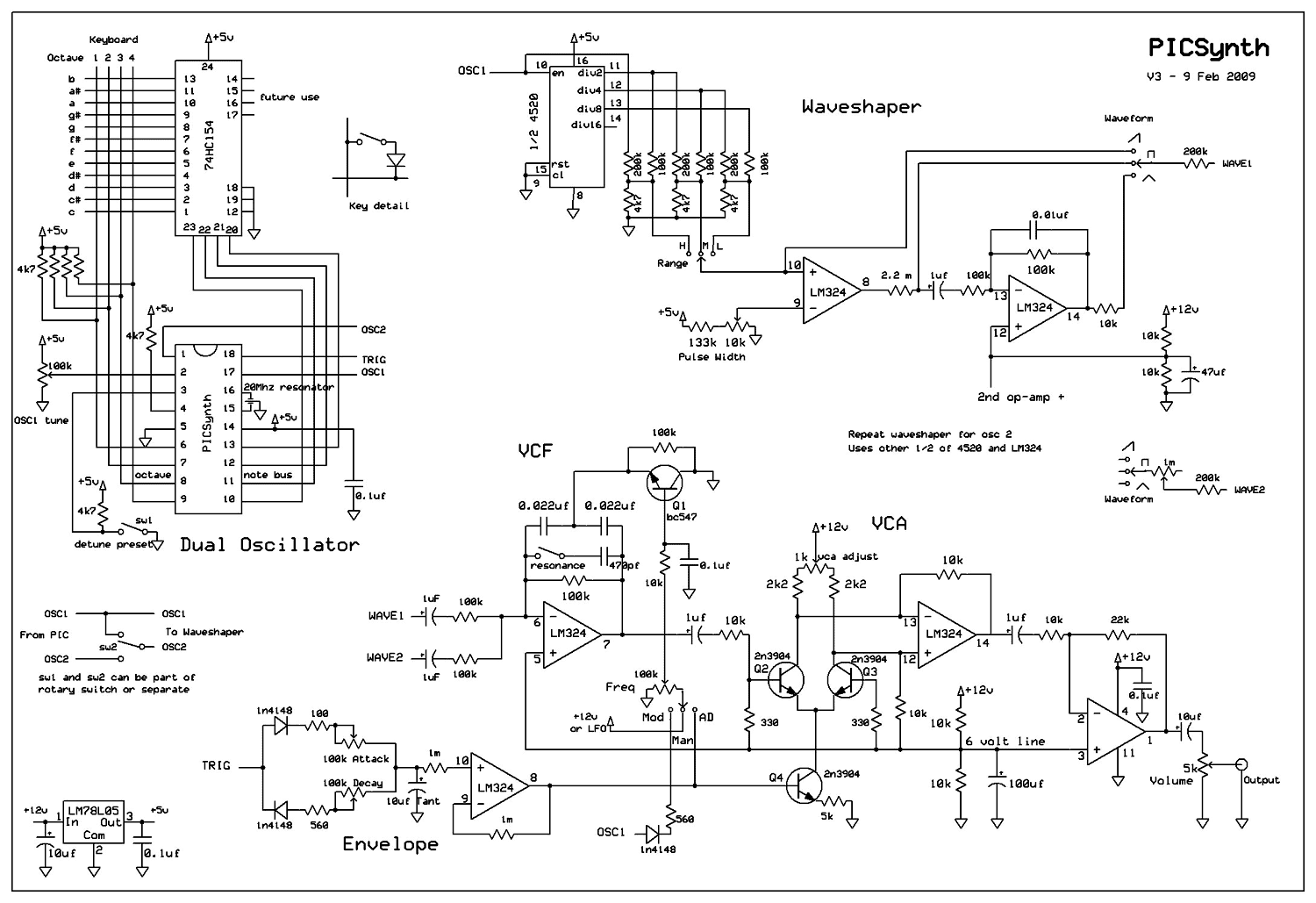
A real analog synthesizer to build using easy to get components, capable of a wide range of sounds. The two oscillators can be detuned for that classic synth sound. Dual oscillator mono synth. Really easy to build using just...
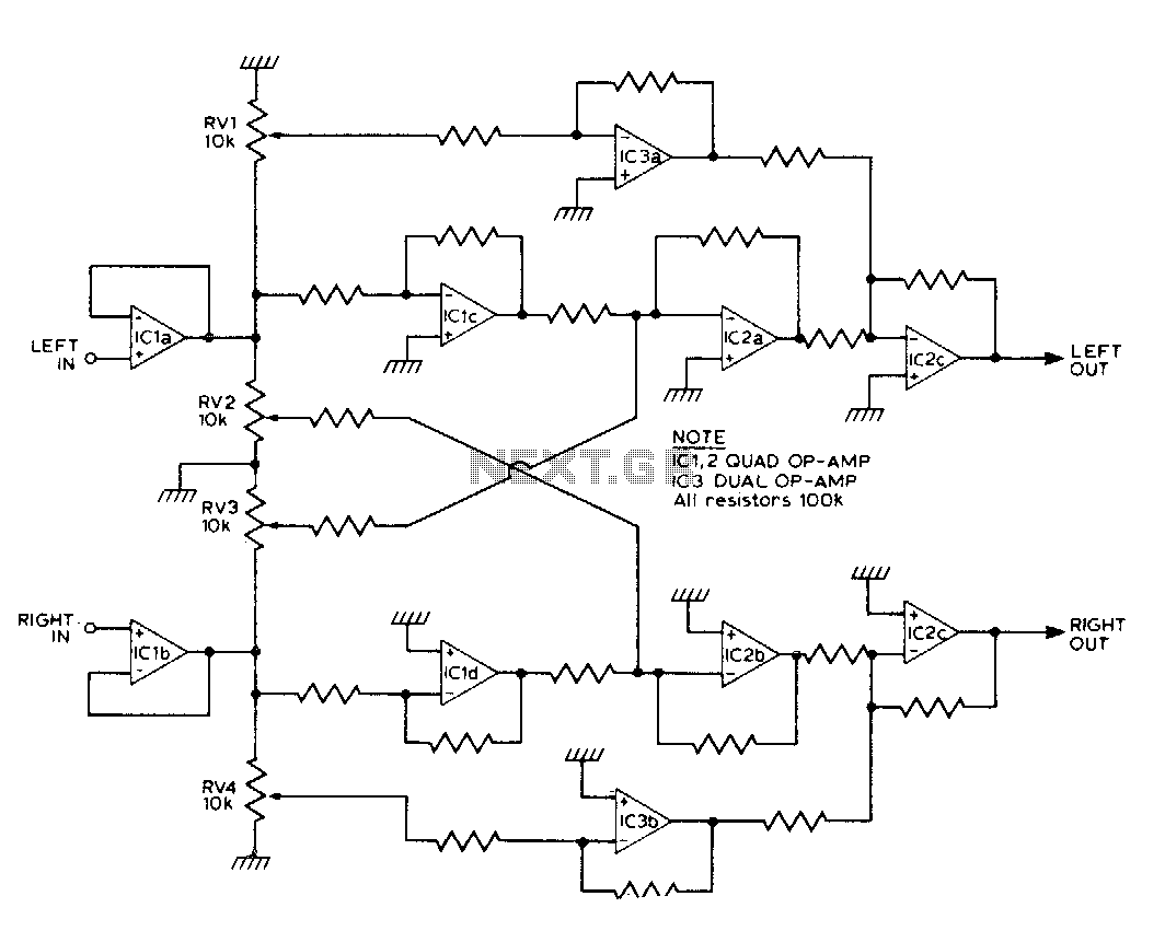
This circuit synthesizes two rear channels for quadraphonic sound when provided with a stereo signal. The rear output for the left channel is created by combining the left channel input, which is 180 degrees out of phase, with a...

The AD9835 combines the Numerical Controlled Oscillator (NCO), COS Look-Up Table, Frequency and Phase Modulators, and a Digital-to-Analog Converter on a single integrated circuit. With more easy words you can say that this circuit is an oscillator where the...