
Tachometer

The described circuit utilizes a standard shaft encoder to generate square wave outputs from its A and B ports, which are crucial for determining the position and direction of rotation of a shaft. The phase relationship between the A and B signals is fundamental, as it indicates the rotational direction; A leads B by 90 degrees when the shaft rotates in one direction and lags by 90 degrees when it rotates in the opposite direction.
To achieve high-resolution measurements, the tachometer circuit is designed to detect every transition in the A and B signals. This is accomplished through the integration of a series of integrated circuit components. The output of IC1A changes state with each transition of the A signal, which generates a corresponding negative pulse at IC1C. These pulses serve as clock signals for a counter, which counts in either direction based on the phase relationship of the A and B signals.
The timing circuit, consisting of resistors R1 and R2 and capacitors C1 and C2, is critical for ensuring the correct timing of the up/down signal relative to the clock edges. The time constant of R1C1 is set to be approximately double that of R2C2, which guarantees sufficient setup and hold times for the counter's up/down signal. IC1C is responsible for generating clock pulses that maintain a consistent duration, regardless of whether the transition is positive or negative.
The exclusive-NOR gate logic implemented in IC1B is vital for determining the correct polarity of the up/down signal. It achieves this by logically combining the A and B signals just before a transition occurs, ensuring that the counter receives the correct direction information at the appropriate time.
Capacitor C1 plays a memory role in this circuit, temporarily holding the voltage level of the B signal for about 2 microseconds, which allows for accurate signal processing during fast transitions. The overall design ensures that the maximum operational frequency for the A and B signals is approximately determined by the formula (4R1C1)⁻¹, allowing for efficient counting and direction detection in high-speed applications.A standard shaft encoder"s A and B ports generate square waves with the same frequency as the shaft turns. The phase of A will lead or lag that of B by 90°, ~depending on the direction of rotation. To obtain maximum resolution, the tachometer circuit must count every change of the state for the A and B signals.
Each such change causes a change of state at IC1A"s output, followed by a 1-!LS negative pulse at the output of IClC. These clock pulses" positive (trailing) edges cause the counter to count up or down, according to the direction of shaft rotation.
You should set the RlCl time constant, so that it is approximately twice that of the R2C2 product, to ensure adequate setup and hold times for the up/down signal with respect to the positive clock edges. IClC supports this timing requirement by producing clock pulses of similar duration for either positive or negative transitions or IC1A.
The exclusive-NOR logic of IC1B generates the correct polarity of the up/down signal when necessary, at the positive clock edges, by combining the A value with the B value just prior to a transition of A or B. Cl provides memory by sorting the B value voltage for about 2 !LS-The maximum frequency for A or B is approximately (4R1Cl)-1.
Related Circuits
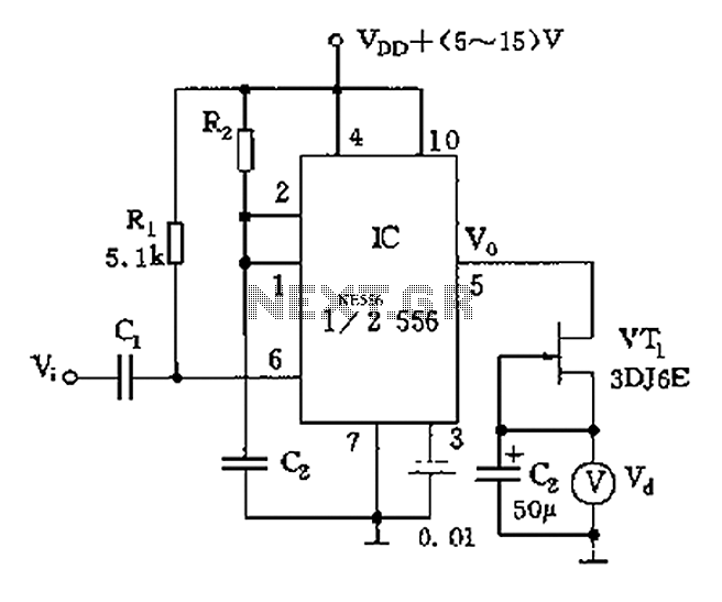
The circuit utilizes switch contacts that are proportional to the speed pulse signal Vi. A differential signal is fed into the trigger side of an integrated circuit (IC), specifically a 555 timer configured in monostable mode (1/2 556), to...
A tachometer can be constructed using the TC9400 in frequency-to-voltage (F/V) mode to convert frequency information (RPM) into a linearly proportional voltage. This voltage can then be compared to one of several comparators (in this example, using eight). The...
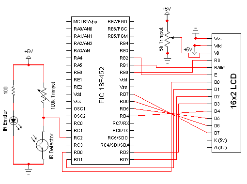
The circuit for the Digital Tachometer/RPM Counter consists of only a few devices. Wire them up according to the following circuit diagram. The PIC used is on a demonstration board, which means the clock, power, and ground pins are...
This circuit illustrates the configuration of an ICM7217 and an ICM7555 designed as a basic frequency counter. The connections between the ICM7217 and a common-cathode LED display are depicted in Figure 12-18. Calibration of the frequency counter is accomplished...
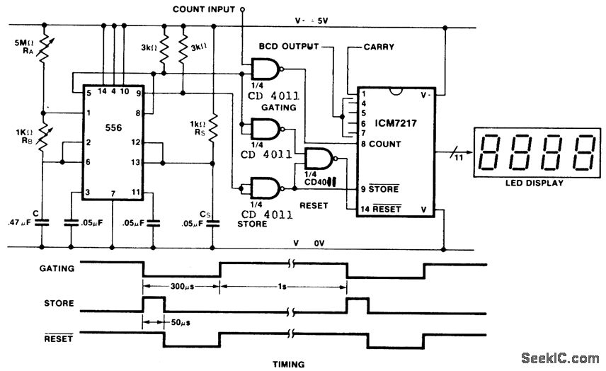
This is an inexpensive frequency counter and tachometer circuit. It utilizes a 556 dual timer to generate the gating, not-store, and not-reset signals for an ICM7217 counter. One timer operates as an astable multivibrator using resistors RA, RB, and...
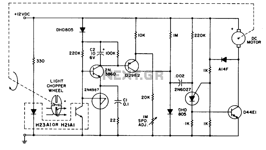
The system employs the H21A1 optocoupler and a chopper disc to achieve enhanced speed regulation. This is effective when the dynamic characteristics of both the motor system and the feedback system are appropriately matched, ensuring stability. The tachometer feedback...