
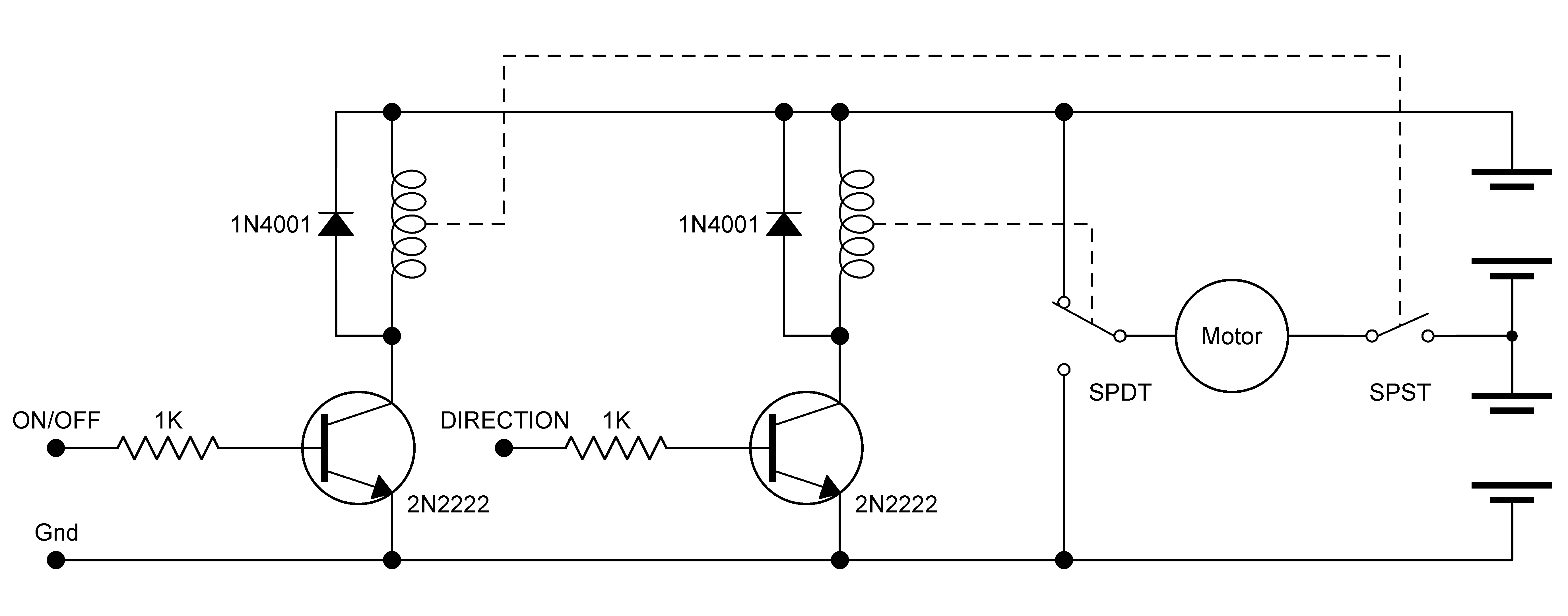
TC649 motor drive circuit with overheat protection

The described circuit design incorporates several critical components to ensure effective motor temperature monitoring and control. The NTC thermistor (RT) serves as a temperature sensor, providing real-time feedback on the motor's operating temperature. As the temperature increases, the resistance of the NTC thermistor decreases, resulting in a corresponding change in the voltage input to the PWM control circuit (IC2). This relationship allows for precise control of the motor's operation based on its thermal state.
The PWM control circuit is configured to modulate the duty cycle of the output signal, which directly influences the speed of the motor. The range of input voltage from 1.2V to 2.6V enables the circuit to accommodate various operating conditions, ensuring optimal performance across different temperature thresholds. The duty cycle is adjusted based on the temperature readings, allowing for gradual increases in speed as the motor cools down and requires less power.
VT1 plays a pivotal role in the circuit by acting as a variable speed controller for the motor. The PWM signal generated by IC2 drives VT1, which regulates the voltage supplied to the motor. This allows for smooth transitions in motor speed, enhancing the overall efficiency of the system.
Current detection is critical for protecting the motor from potential damage due to excessive current draw. The inclusion of feedback through resistor R6 allows for monitoring and limiting the current flowing through the motor, ensuring that it operates within safe parameters. If the current exceeds predetermined levels, the circuit can trigger an automatic shutdown to prevent overheating and potential failure.
Overall, this motor overheating protection and drive circuit exemplifies a robust design that integrates temperature sensing, PWM control, and current limiting features, making it suitable for various applications, including fan motors and other larger loads. The careful selection of components and design strategies ensures reliable operation and enhanced safety for motor-driven devices.Motor is heating devices, by accident or overload often caused when the coil winding temperature is too high, as shown in FIG. 1-9 TC649 motor overheating protection and drive circuit. NTC thermistor RT close to the motor of the motor temperature detection, RT, James I, R2 determine the IC2 input into the PWM control voltage VIN, setting range is generally 1.2 ~ 2.6V, the output voltage control output K points (pulse width modulation duty cycle) signal (range of O ~ 100%). For example, 30C when, VIN = 1.9V, the duty cycle is 50qo; when 60qC, VIN = 2, 6V, 100% duty cycle; after changing the motor speed VT1 driven by the PWM signal.
feet for the current detection, for limiting the size of the motor current flowing through the motor or VT1 generated by the current pressure on the R6 drop by c5 feedback to feet, the maximum output current of the motor control. feet set up automatic shutdown threshold level. Suitably selected VT1 and supply voltage, the circuit can drive a fan motor or larger loads.
Related Circuits
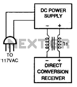
One solution for AC power line hum and ripple, which is caused by leakage current, is to utilize a well-regulated and filtered 9 to 18 VDC power supply that incorporates a balancing choke (Tl in this illustration) between the...
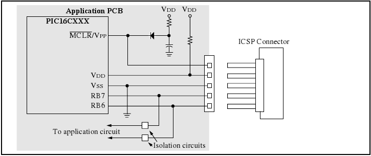
The programmer utilizes a serial signaling scheme to program the chip while it is in-circuit. The signaling is transmitted through the programming clock (PGC or ICSPCLK) and the programming data (PGD or ICSPDAT) pins. Additionally, the MCLR/VPP pin serves...
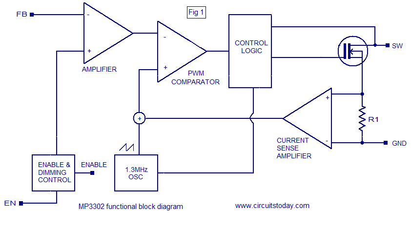
The MP3302 is a boost converter integrated circuit (IC) specifically designed for LED drive applications. It is capable of driving 27 LEDs, arranged as 9 strings of 3 white LEDs in series, powered by a lithium-ion battery. The IC...
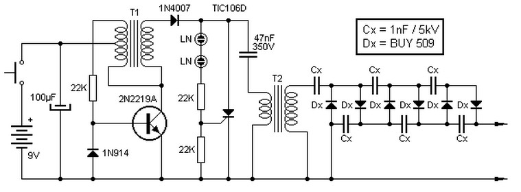
This high voltage source consists of an inverter built around a transistor that generates pulses of 150V. These pulses are supplied to an inverter made of a thyristor and a capacitor, which is connected in series with transformer T2....
Bridges enable robots to control high-current motors by connecting the low-current logic circuitry of the robot's brain to the high current required by the motors. Many bridges utilize the common "H" arrangement of control circuitry, typically involving power transistors,...
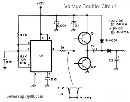
The schematic diagram originates from a 12V DC voltage doubler circuit power supply. This circuit diagram illustrates a DC voltage doubler/DC converter that transforms a 12V DC power supply into 24V DC and 18V DC outputs. It is compatible...