
TDA7000 FM Radio IC Test Circuit and Datasheet

The TDA7000 integrated circuit is engineered for use in FM radio applications, providing a compact solution that integrates multiple essential functions into a single chip. The Frequency-Locked Loop (FLL) system allows for stable frequency tuning, which is crucial for maintaining clear audio reception. The RF input stage amplifies incoming radio signals, ensuring that weak signals can be adequately processed.
The mixer component within the TDA7000 combines the RF signal with a local oscillator signal to produce an intermediate frequency (IF) of 70 kHz. This IF signal is then demodulated by the IF demodulator to extract the audio information, which can subsequently be amplified for output. The mute detector and mute switch functionalities enable the radio to automatically mute the audio output during periods of weak signal reception or silence, enhancing the user experience by reducing unwanted noise.
In terms of physical design, the TDA7000 is typically implemented on a printed circuit board (PCB), where careful attention must be paid to the component layout to minimize interference and optimize performance. The datasheet provides comprehensive details on the recommended PCB layout, including the placement of components to ensure signal integrity and reduce parasitic effects.
Additionally, the package outline information is crucial for ensuring compatibility with existing designs and for proper thermal management. The maximum permissible temperature for soldering is specified to prevent damage to the IC during assembly. Repairing soldered joints is also addressed in the datasheet, providing guidance on best practices to ensure reliable connections and maintain performance over the lifespan of the device.
Overall, the TDA7000 serves as a versatile and efficient solution for FM radio applications, with its integrated design simplifying the development process for engineers and hobbyists alike.TDA7000 is an IC for FM portable radios which has a Frequency-Locked-Loop system with an intermediate frequency of 70kHz. The TDA7000 has the following functions: RF input stage, mixer, local oscilator, IF demodulator, mute detector and mute switch.
The diagram below shows you with the block diagram of this FM radio monolithic IC. For printed-circ uit boards, component layout used for the circuit, package outline, maximum permissible temperature of the solder, and repairing soldered joints can be seen in the TDA7000 datasheet (source: nxp. com) 🔗 External reference
Related Circuits
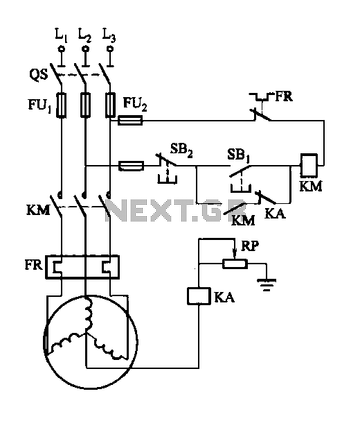
A potentiometer (RP) is utilized for adjusting the operating voltage of the relay (KA) to ensure that the motor operates normally, especially when the relay (KA) does not function reliably during the action phase. The circuit involves a potentiometer...
The circuit contributes 3.2 nV/√Hz of voltage noise and 0.45 pA/√Hz of current noise. To minimize noise from other sources, resistor R3 is configured to 100 ohms, resulting in an additional voltage noise of only 1.3 nV/√Hz. Resistors R1,...
The figure below illustrates a schematic of a highly sensitive microphone circuit designed to amplify faint sounds from a distance. The circuit exhibits significant sensitivity and offers substantial gain to weak audio signals. The microphone circuit typically consists of several...
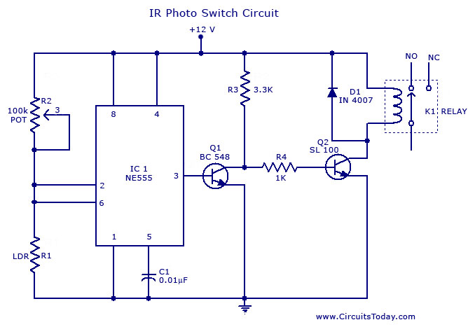
A simple photo switch circuit using the NE555 IC with a diagram and schematic. This photo switch activates a relay when light intensity exceeds a certain threshold. It serves as a light sensor circuit suitable for both home and...
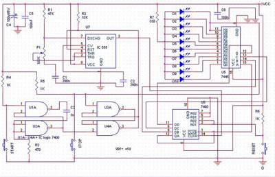
The speed test circuit is a simple design intended to measure a person's reaction time in a game. The operation of this peripheral is straightforward, facilitated by several integrated circuits, including a counter, timer IC, and decoder. The timer...
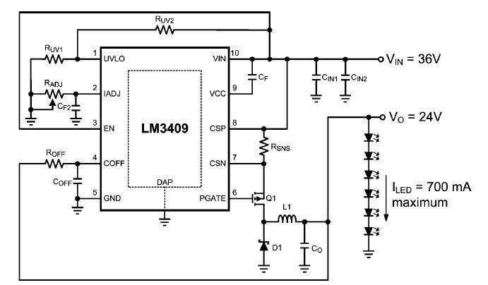
This dimming-controlled LED driver electronic circuit requires an input voltage of 36 volts and will provide an output voltage of 24 volts at a maximum current of 700 mA. The described dimming-controlled LED driver circuit is designed to efficiently convert...