
tda7384 class ab audio power amplifier circuit design electronic project

The input capacitor plays a crucial role in filtering unwanted low-frequency signals in electronic circuits. By selecting a capacitance of 0.1 µF, the circuit is designed to attenuate frequencies below 16 Hz, effectively blocking DC components and allowing only AC signals above this threshold to pass through. This is particularly important in audio applications, where low-frequency noise can interfere with signal integrity.
The cut-off frequency (fc) can be calculated using the formula:
fc = 1 / (2πRC)
where R is the resistance in ohms and C is the capacitance in farads. In scenarios where the resistance value (R) is known, the selection of a 0.1 µF capacitor will ensure that the circuit operates effectively above the specified cut-off frequency.
In practical applications, the input capacitor is typically connected in series with the signal path. This configuration allows the capacitor to block any DC offset present in the input signal while permitting the desired AC signal to reach subsequent stages of the circuit, such as amplifiers or filters.
It is also essential to consider the voltage rating of the capacitor to ensure it can withstand the applied voltage without failure. Additionally, the choice of capacitor type, whether ceramic, electrolytic, or film, can influence the performance characteristics, including frequency response and equivalent series resistance (ESR).
Overall, the input capacitor is a critical component in achieving desired frequency response and signal integrity in various electronic applications.The input capacitor is for the low frequency cut-off and the standard value for the input capacitors is 0. 1uF ( the cut-off for this value is amount to 16Hz). 🔗 External reference
Related Circuits
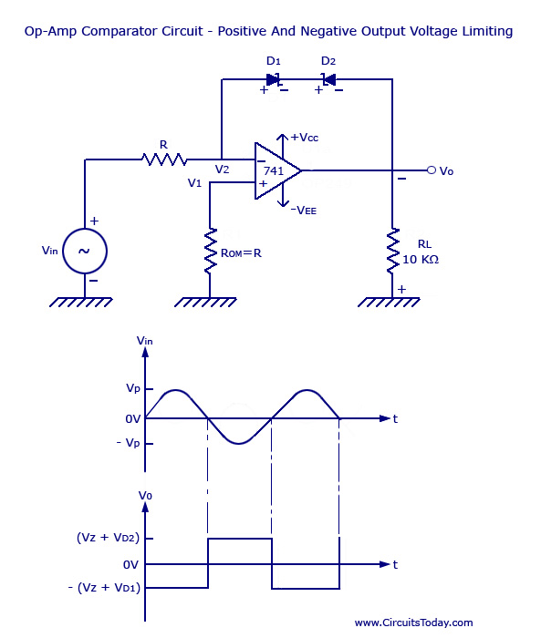
Voltage Limiter Circuit Using Op-amp - Circuit Diagram, Waveform, Positive and Negative Voltage Limiters. The voltage limiter circuit utilizing an operational amplifier (op-amp) serves to restrict the output voltage to predefined levels, effectively preventing it from exceeding or falling below...
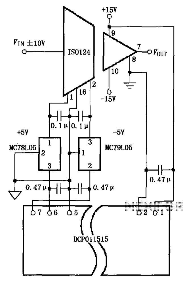
The circuit depicted in the figure includes the ISO124 and MC78L05 components, along with an external regulator, MC79L05, and the DCP011515, which collectively enhance the power supply rejection ratio (PSR) of the circuit. The input signal, VIN (maximum swing...
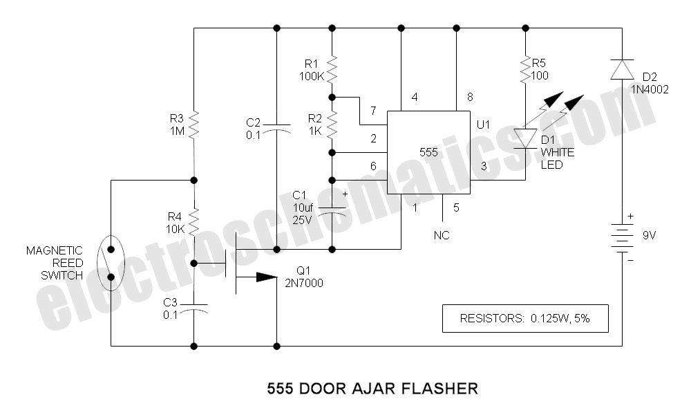
This is a compact LED flasher circuit designed using the 555 timer integrated circuit (IC), powered by two 1.5V batteries. The circuit can function as a flashing metronome, dark room timer, reminder, or for other similar applications. In the...
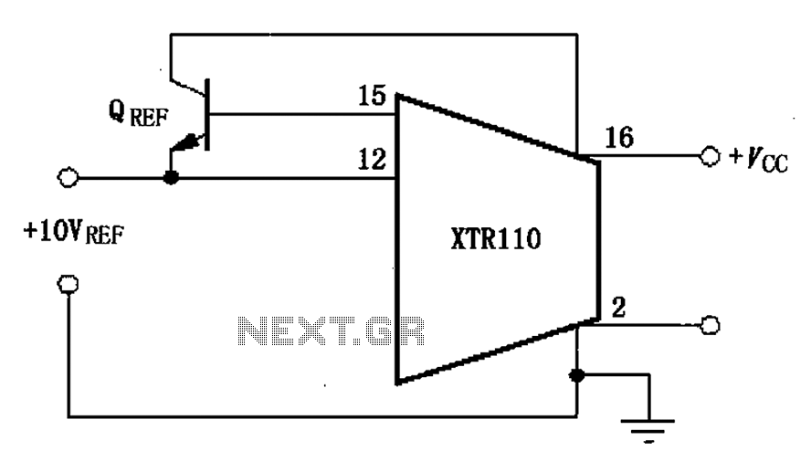
The XTR110 features an internal voltage reference that can output a current of 10mA. By incorporating an external NPN transistor, designated as QREF, the output current capability can be increased. When the VCC voltage reaches 40V, a 2N3055 transistor...
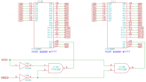
The memory component of the Mark 2 system is quite straightforward. It consists of two 32K SRAM chips, which are actually FRAM due to availability, but this does not impact functionality in this context. The selection of these chips...
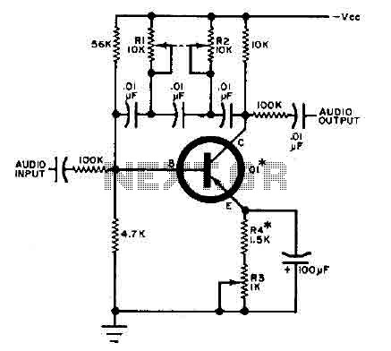
This circuit is designed for selective tuning adjustments between two closely spaced audio tones. The frequency of the circuit is determined by the selected capacitors and resistors in the feedback loop between the collector and base of transistor Q1....