
telephone call voice changer

The described circuit operates as a comprehensive audio processing system, integrating several critical components to ensure optimal performance and flexibility. The variable gain microphone preamplifier, implemented with IC1A, provides adjustable amplification to accommodate various microphone types and input signal levels. This feature is essential in applications where different microphones may be used, each with its inherent sensitivity and output characteristics.
The inclusion of a variable steep Wien-bridge pass-band filter, facilitated by IC1B, allows for precise frequency selection centered around 1 kHz. This frequency is typically where vocal clarity is paramount, making it ideal for voice applications. The filter's ability to be bypassed via switches SW1A and SW1B offers users the option to either process the microphone signal through the filter or to route it directly to the outputs, enhancing the circuit's versatility.
Resistor R3 plays a crucial role in determining the gain of the microphone preamplifier. By adjusting R3, users can tailor the amplification level to suit specific needs, while also introducing controlled distortion. This capability can be particularly beneficial for applications requiring a more authentic representation of voice, such as in telecommunications, where the sound quality must mimic that of a traditional phone call.
The steepness control provided by resistor R9 is another significant aspect of the circuit design. Careful adjustment of this resistor is necessary to achieve the desired filter characteristics without introducing undesirable artifacts such as ringing. Ringing can occur when the filter's steepness is set too high, leading to overshoot and oscillations in the output signal. Therefore, a balanced approach to tuning R9 is essential to maintain audio fidelity while achieving the intended filtering effects.
Overall, this circuit design effectively combines a variable gain microphone preamplifier, a flexible pass-band filter, and an audio amplifier to create a robust audio processing solution suitable for various applications, particularly in voice communication systems.This design fulfills these requirements by means of a variable gain microphone preamplifier built around IC1A, a variable steep Wien-bridge pass-band filter centered at about 1KHz provided by IC1B and an audio amplifier chip (IC2) driving the loudspeaker. 1) The pass-band filter can be bypassed by means of SW1A and B: in this case, a non-manipulat ed microphone signal will be directly available at the line or loudspeaker outputs after some amplification through IC1A. 2) R3 sets the gain of the microphone preamp. Besides setting the microphone gain, this control can be of some utility in adding some amount of distortion to the signal, thus allowing a more realistic imitation of a telephone call voice.
3) R9 is the steep control of the pass-band filter. It should be used with care, in order to avoid excessive ringing when filter steepness is approaching maximum value. 🔗 External reference
Related Circuits
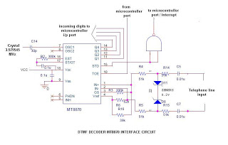
This is a straightforward circuit utilizing the DTMF decoder MT8870 (or CM8870). As illustrated in the circuit, an interrupt will be generated (if the NAND output is connected to the INT of the microcontroller) whenever a call is received...
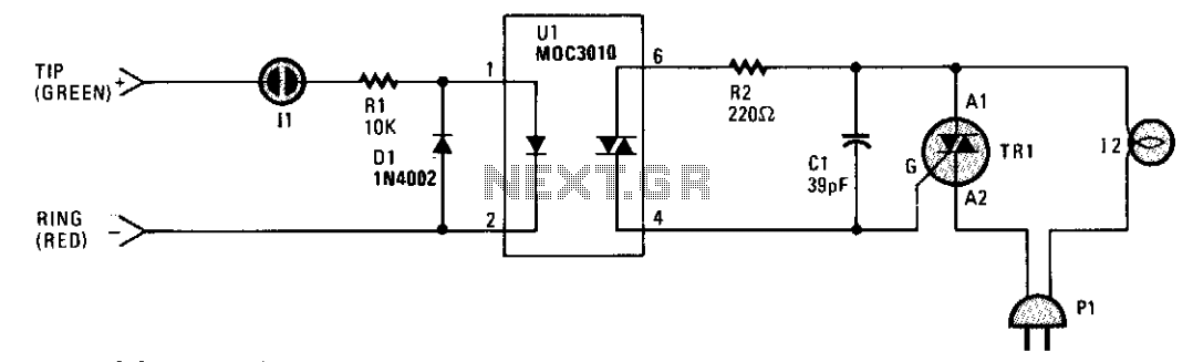
A small neon lamp is activated by the telephone's ringing voltage, allowing a sufficient current to flow to the LED in optocoupler U1. This activation subsequently triggers a 6-A Triac that controls a 117-Vac lamp or bell. Capacitor C1...
The yellow wires on the far right serve as temporary power connections, allowing battery power to enter through the contact studs located in the large holes that press against the radio's battery terminals. The cable in the lower right...

Controlling devices using switches is common. Over the past few decades, remote control switches such as infrared remote control switches, wireless remote control switches, and light-activated switches have gained popularity. However, these technologies have their limitations. Laser beams can...
This circuit is a modification of a high and low voltage cut-off with delay and alarm circuit that was featured in Circuits Today. It has been tested and found to be reliable. The circuit can be adapted with minor...
This project utilizes the ISD2560P integrated circuit (IC), which enables the recording of 60 seconds of audio and subsequent playback with high fidelity. The schematic indicates that the input source is an electret microphone. If a dynamic microphone is...