
Three phase auto changer circuit

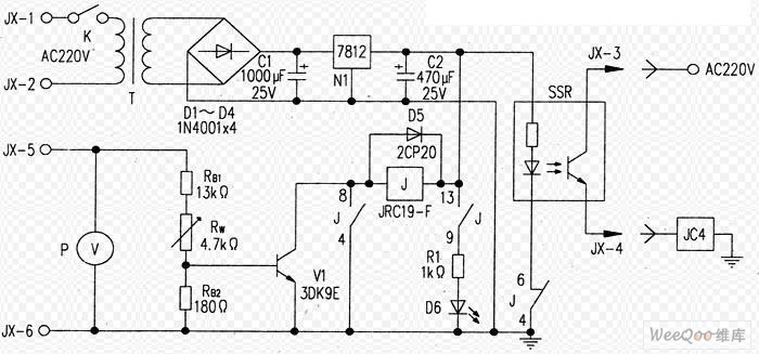
This circuit serves as a voltage monitoring and control system designed to protect electrical and electronic devices from voltage fluctuations. The primary components include a transformer, a relay, and a delay mechanism. The transformer steps down the mains voltage to the required levels, providing a secondary output of 15-0-15 AC volts at 500mA, which is essential for the operation of the relay.
The relay acts as a switch that can open or close the circuit based on the input voltage levels. The high and low voltage cut-off features enable the circuit to disconnect the load when the voltage exceeds or drops below predefined thresholds. This is critical in preventing damage to sensitive equipment that may be adversely affected by voltage levels outside of their specified operating range.
The delay feature in the circuit ensures that transient voltage spikes do not trigger the relay unnecessarily. This is particularly important in environments where voltage fluctuations are common. The delay allows for a brief period during which the voltage can stabilize before the circuit takes action.
An alarm system can be integrated into the circuit to provide an audible or visible alert when the voltage exceeds or falls below the set thresholds. This serves as an additional layer of notification for users, allowing them to take corrective action if necessary.
Overall, this circuit is adaptable for various applications and can be modified to suit specific requirements, such as adjusting the cut-off voltage levels or incorporating different relay specifications to accommodate various load types. Proper implementation of this circuit can significantly enhance the reliability and longevity of electrical and electronic equipment by safeguarding against voltage irregularities.This circuit is a modification of High & Low voltage cut-off with delay& alarm circuit appeared in Circuits today, which I have tried and found to be quite reliable. You can adopt this circuit with small modification. Use a transformer with secondary 15 0 15 AC Volt at 500mA, for 18Volt relay opera tion. Normally any modern electrical / electronic equipment can operate with 230 Volt ± 15% AC supply. That is, it can stand normal voltage operating range of 195 to 265 Volts. It may misbehave beyond this voltage range. You can choose the practical voltage required for the low end high cut off to change over to other phase. 🔗 External reference
Related Circuits
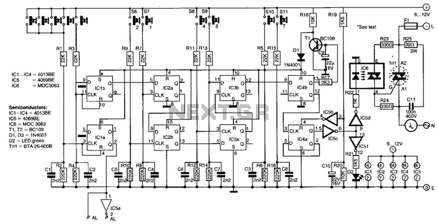
This switch utilizes four CD4013BE dual flip-flops, an inverter, and an optoisolator to control a triac, allowing it to switch a 25-A AC load current. A standard 4x3 telephone keypad is employed for entering a 6-digit code. In the...
The FM302E-I-type FM transmitter exciter is manufactured by NEC Corporation, Japan, and features a 1210 motherboard. It utilizes direct frequency modulation of the carrier signal, employing phase-locked frequency stabilization and frequency synthesis techniques. The front power amplifier is based...
This complete aerial quality, low noise address audio amplifier is based on the Hybrid Integrated Circuit STK4050 manufactured by Sanyo. The circuit incorporates all necessary components and has a maximum output power of 200W. It features an onboard power...
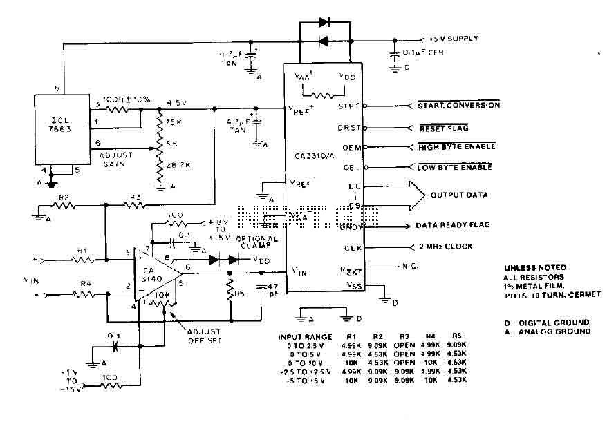
The BiMOS CA3140 operational amplifier offers excellent orientation capabilities for high bandwidth signal inputs and can swiftly adjust the energy output at its terminal CA33IO WINE. The CA3140 can also operate close to the negative supply rail. If the...
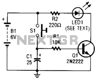
Used as a 10-second momentary illuminator, this circuit can be useful in other applications as well. Pressing SI charges CI, which holds Q1 on and keeps the LED lit for about 10 seconds. The circuit described functions as a momentary...
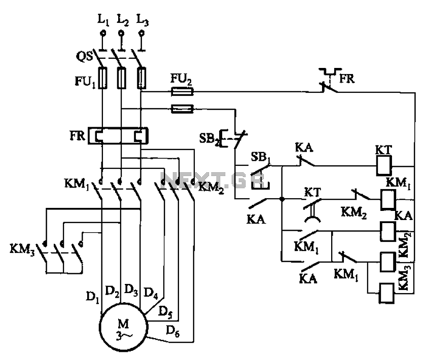
The circuit depicted in Figure 3-99 illustrates a low start-up mechanism for a motor, which transitions to high-speed operation automatically. The start-up process is facilitated by a shaped connection, while the transition to high-speed operation is managed by a...