
Telephone-controlled tape starter

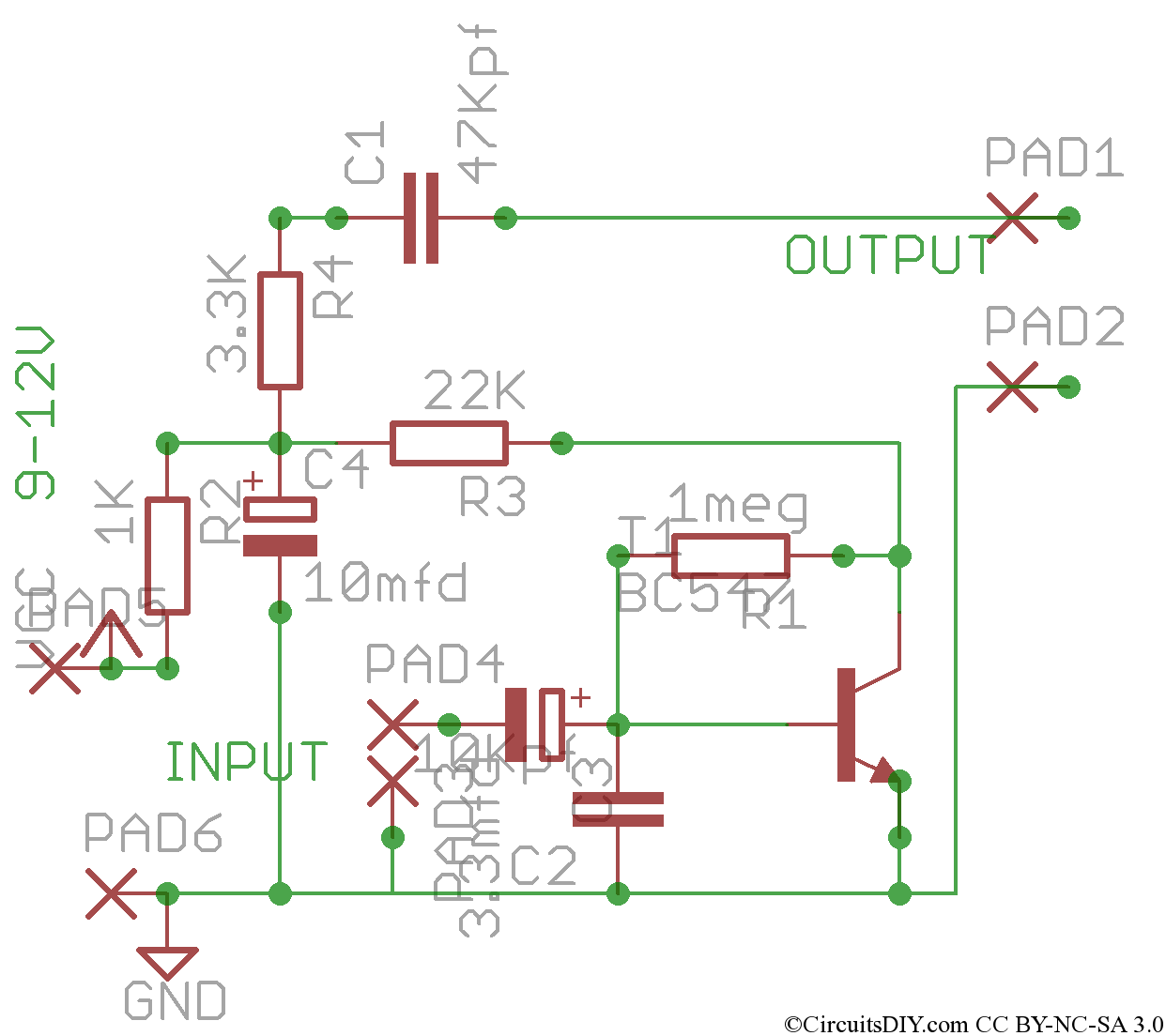
This circuit operates by utilizing the voltage characteristics of a standard telephone line to control the recording device. The two Darlington transistors, Q1 and Q2, are configured to provide a high current gain, ensuring that even a small change in voltage at the base of Q1 can switch the tape recorder on or off effectively. Resistors R1, R2, and R4 play a crucial role in setting the biasing conditions for Q1, ensuring that it remains off when the phone is on-hook due to the high DC voltage present.
When the receiver is lifted, the voltage drop across the phone line reduces the biasing voltage at the base of Q1, allowing it to turn on. This action, in turn, activates Q2, which completes the circuit to the tape recorder, allowing it to start recording. The design ensures that no external power source is necessary, as it relies solely on the existing telephone line voltage, making it a practical solution for automatic recording without the need for additional batteries or power supplies.
The circuit's simplicity and reliance on passive components make it an efficient design for users seeking to record telephone conversations automatically. Care should be taken to ensure that the components are rated appropriately for the voltages involved, and that the circuit is housed in a suitable enclosure to prevent accidental short circuits or interference with normal telephone operation.This circuit converts a tape recorder into a completely automatic telephone conversation recording instrument that needs no external power source. Voltage at the switch terminals of tape recorder applied to a pair of Darlington-connected transistors, Ql and Q2, will turn on and start the tape recorder.
To turn the transistors off, and thereby stop the machine, apply a negative voltage to the base of Ql from the phone line When the telephone receiver is on the hook, there is typically about 50 volts dc across the phone divided across Rl, R2, and R4 in such a way that the base of Ql is sufficiently negative to keep the tape recorder off. When the phone"s receiver is picked up, the voltage on the telephone line drops to about 5 volts, which leaves-insufficient negative voltage on the base of Ql to keep it cut off, so the tape recorder starts and begins to record.
Related Circuits
Nissan Sentra 1.6 Liter Manual Transmission Starter Circuit Wiring Diagram. The Nissan Sentra 1.6 Liter manual transmission starter circuit wiring diagram provides a visual representation of the electrical connections involved in the starting system of the vehicle. This diagram is...
This circuit consists of a single transistor functioning as an amplifier, providing significant amplification for weak and unipolar signals, which can then be fed into a more powerful amplifier. The described circuit utilizes a single transistor in a common-emitter...
The Stereo Tape Head Preamplifier kit is based on LA3161 IC from SANYO. Power supply - 9 ~ 12 VDC @ 20 mA. Output power - upto 200 mW. Input Resistance - 100 KΩ (Typ), Load Resistance - 10...
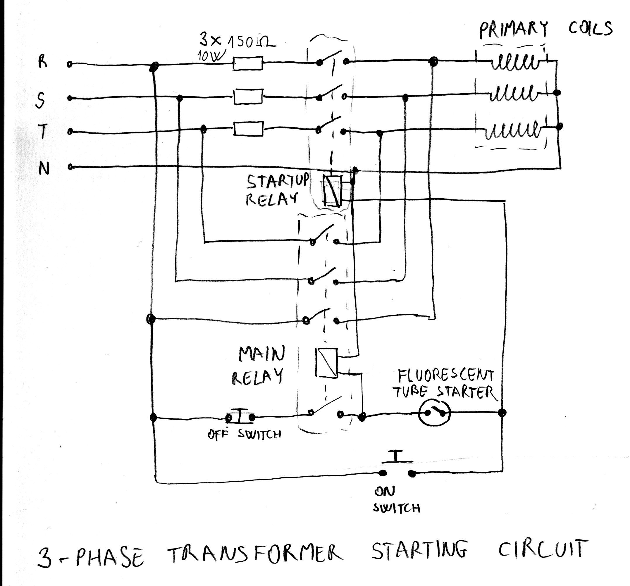
After acquiring a large 3-phase variable transformer (variac), there was an unexpected issue with it tripping circuit breakers at random when plugged in. Interestingly, the tripping occurred on different phases and seldom affected all three simultaneously. Resetting the breakers...
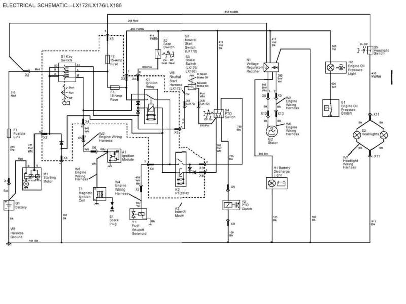
The JD mower has been experiencing inconsistent starting issues. The starter occasionally activates, but more frequently it does not. After a prolonged wait, it may start. A suggestion was found online to add a relay to the circuit, as...
This motor starter safeguards single-phase motors from voltage fluctuations and overloads. A key feature is the soft on/off electronic switch, which facilitates user operation. The transformer reduces the AC voltage from 230V to 15V. Diodes D1 and D2 convert...