
Electronic Motor Starter

This motor starter circuit is designed to enhance the operational reliability of single-phase motors by incorporating several protective features. The transformer is crucial for reducing the mains voltage to a safer level, which is essential for the subsequent circuitry. The rectification process performed by diodes D1 and D2 ensures that the power supply is suitable for the protection circuit, converting AC to DC for stable operation.
The protection circuit is the heart of this design. Transistor T1 monitors the voltage level, and its adjustable threshold allows for customization based on the specific motor's requirements. This flexibility is vital for ensuring that the motor operates within safe voltage limits, preventing damage due to over-voltage conditions. Similarly, T2 acts as a safeguard against under-voltage scenarios, ensuring the motor is not subjected to insufficient voltage, which could lead to inefficient operation or damage.
Zener diodes ZD1 and ZD2 play a critical role in biasing the transistors, ensuring they operate correctly within their intended regions. The SCR-like configuration formed by T3 and T4 allows for efficient control of the motor's power state, enabling smooth transitions between on and off states.
The inclusion of switches S1 and S2 provides a user-friendly interface for manual control of the motor. The temporary disconnection of capacitor C2 during voltage adjustments is a practical design consideration, allowing for accurate settings without interference from transient voltage spikes.
The use of the regulator IC 7809 ensures that the soft switch and relay receive a stable voltage supply, which is essential for reliable operation. Capacitor C4 serves to filter any residual noise, further stabilizing the power supply.
The miniature circuit breaker is an important safety feature, providing automatic disconnection in the event of an over-current situation, thus protecting both the motor and the circuit from potential damage.
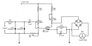
Finally, the status indicators (LED1 and LED2) allow for immediate visual feedback regarding the operational state of the motor and the power supply, enhancing user awareness and operational safety. Overall, this motor starter circuit is a well-designed solution for managing the performance and safety of single-phase motors in various applications.This motor starter protects single-phase motors against voltage fluctuations and overloading. Its salient feature is a soft on/off electronic switch for easy operation. The transformer steps down the AC voltage from 230V to 15V. Diodes D1 and D2 rectify the AC voltage to DC. The unregulated power supply is given to the protection circuit. In the p rotection circuit, transistor T1 is used to protect the motor from over-voltage. The over-voltage setting is done using preset VR1 such that T1 conducts when voltages goes beyond upper limit (say, 260V). When T1 conducts, it switches off T2. Transistor T2 works as the under-voltage protector. The under-voltage setting is done with the help of preset VR2 such that T2 stops conducting when voltage is below lower limit (say, 180V).
Zener diodes ZD1 and ZD2 provide base bias to transistors T1 and T2, respectively. Transistors T3 and T4 are connected back to back to form an SCR configuration, which behaves as an on`/off` control. Switch S1 is used to turn on the pump, while switch S2 is used to turn off the pump. While making over-/under-voltage setting, disconnect C2 temporarily. Capacitor C2 prevents relay chattering due to rapid voltage fluctuations. Regulator IC 7809 gives the 9V regulated supply to soft switch as well as the relay after filtering by capacitor C4.
A suitable miniature circuit breaker is used for automatic over-current protection. Green LED (LED1) indicates that the motor is on` and red LED (LED2) indicates that the power is on`. The motor is connected to the normally-open contact of the relay. When the relay energizes, the motor turns on. 🔗 External reference
Related Circuits
This circuit is connected to a motorcycle and is integrated into a circuit that is powered only when the key is in the "ON" position. If the motorcycle is turned off using the kill switch while the key remains...
An electronic version of a chirping canary. It may be used as an alarm, a sound effects generator, or perhaps a replacement doorbell. The electronic chirping canary functions as an auditory signaling device, capable of generating a variety of chirping...

The construction and operation of brushless motor windings are based on the principle of triangular coils. Through the switch, the stator coil current can be cycled, resulting in the formation of a rotating magnetic field. The cycle of the...
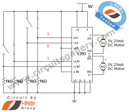
How can a DC motor be rotated in clockwise and counterclockwise directions? This is a common question posed by many robotics beginners. DC motor driver circuits are essential components in robotics workshops. The L293D IC is frequently utilized for...

The automatic electronic circuit depicted in the figure consists primarily of a voice circuit, an oscillation circuit, and a driving section for the display circuit. The automatic electronic circuit integrates several essential components to achieve its functionality. The voice circuit...
The electronic tachometer frequency converter circuit operates by converting the input signal into a proportional current that can be measured by a pointer device. The electronic tachometer frequency converter circuit is designed to accurately measure the rotational speed of a...