
telephone dtmf remote control

The circuit operates as follows: after detecting the dial tone from the phone, the user presses 0 on the phone remotely. The KT3170 (IC1) decodes this signal, activating pin 11 of the 74 154 (IC2) to a low state. This low state triggers the normally open (NO) contact of the CD4023 (IC3), which then transitions to a high state. Consequently, the flip-flop IC5a is toggled, activating the transistor Q1. This action energizes the relay K1, closing its two contacts, C1 and C2. The C1 contact, with a resistance of 220 Ohms, creates a loop through the phone line to disconnect the ringing signal, simulating the phone being taken off the hook. The C2 contact connects a 10 kHz audio source to the telephone line, indicating that the system is now in remote switch mode.
When a key is pressed on the transmitter, for instance, pressing 1, IC1 decodes this as 0001, bringing pin 2 of IC2 low. The corresponding NO contact within IC3 then transitions to a high state, switching the flip-flop IC5b and activating transistor Q2. This action energizes the relay, thereby switching the connected device through its contacts. Pressing keys 1 through 9 on the telephone transmitter allows for the control of devices connected to channels O2 through O9. Upon completion of the operation, pressing the 0 key on the telephone transmitter deactivates the flip-flop IC5a, which in turn deactivates relay K1. The 220 Ohm loop is disconnected, the 10 kHz audio source is removed, and the phone is restored to a state ready to receive new calls.
This circuit effectively integrates DTMF technology with relay control, allowing for versatile remote operation of multiple devices through simple telephone interaction. The design is efficient, utilizing standard ICs for decoding and control, making it suitable for various applications in home automation and remote device management.The circuit is a remotely operated DTMF telephone. The circuit can be used to change up to 9 devices using the keys 0 to 9 phone. Digit 0 is used to switch between the phone system remotely and change the way of normal conversation. IC KT3170 (DTMF to BCD decoder) is used to decode DTMF signals transmitted through the telephone line to the corresp
onding BCD format. IC 74 154 (4 to 16 demultiplexer) and IC CD4023 (dual flip flop) is used to change the device according to the DTMF signal reception. Circuit operation is as follows. After hearing the dial tone from the phone at the end of the receiver, press 0 on the phone remotely.
IC1 decodes this as the pin 11 of IC2 1010. The investment will be low and after the door of NO in the IC3 will be high. This will change the flip flop IC5a and the transistor Q1 is activated. This causes the K1 relay ON. The two contacts C1 and C2 of relay K1 is closed. C1 220 Ohm form a loop through the phone line to disconnect the ringing of the telephone line (this condition is similar to taking the phone off the hook). C2 is connected to a source of 10 KHz audio to the telephone line to inform you that the system is now in the way remote switch.
Now if you press a transmitter in the phone, IC1 will decode as 0001 and pin 2 of IC2 is low. After the investment by NO within IC3 corresponding door, which will be high. This will change IC5b flip flop and turns on transistor Q2. The relay is activated and the device connected through its contacts are switched. Pressing the 1 key will change the status of the device. In the same ways Keys 2-9 on the telephone transmitter can be used to change the status of the device connected to channel O2 O9. After the connection has finished, press the O key on the telephone transmitter to change the flip flop IC5a to deactivate the relay K1.
200 Ohm loop line is disconnected, the source of 10 kHz audio will be removed and the phone is ready to receive new calls. 🔗 External reference
Related Circuits

High brightness (HB) and super HB LEDs are utilized in LCD TFT backlighting for high-end televisions, industrial lighting, and projectors. A notable application is in instrument panel backlighting, interior lighting, and brake lights of various vehicles. Luxury automobile manufacturers...
This circuit is the result of research conducted by Andy Collinson. It employs a photodiode, specifically the SFH2030, as an infrared sensor. A MOSFET operational amplifier, CA3140, is utilized in differential mode to amplify the current pulses generated by...
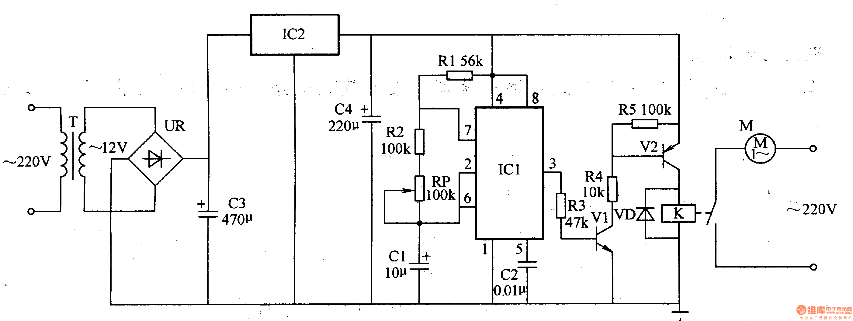
The medical ventilator controller circuit consists of an astable oscillator, a control circuit, and a power supply circuit. The astable oscillator is constructed using resistors R1, R2, a potentiometer RP, capacitors C1, C2, and a time base integrated circuit...
Many a times one needs an extra telephone ringer in an adjoining room to know if there is an incoming call. For example, if the telephone is installed in the drawing room you may need an extra ringer in...
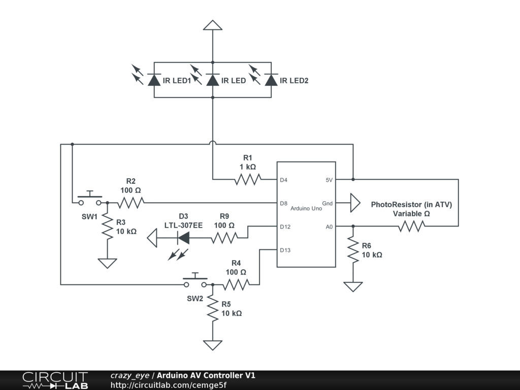
Arduino Event-Driven Universal AV Remote May 1st, 2013. Turn everything on with Airplay. The project involves the development of an Arduino-based universal remote control designed to manage various audio-visual (AV) components through an event-driven architecture. This remote utilizes Airplay...
A circuit designed to extract and measure the modulated carrier of an infrared remote control. This circuit amplifies the entire received signal, allowing the waveform to be displayed on an oscilloscope or a frequency counter. It can measure modulation...