
Audio and Visual Telephone ringer

The circuit described serves as an additional telephone ringer, ideal for use in a separate room from the main telephone unit. The design emphasizes simplicity and ease of installation, as it connects in parallel with existing telephone lines using twin flexible wires, thus eliminating the need for an external power source.
The circuit's functionality is centered around the audio ringer that utilizes the BA8204 or ML8204 integrated circuit, which is specifically engineered for generating bell sounds in telecommunication applications. The IC is packaged in an 8-pin mini DIP form factor, making it compact and convenient for integration into various setups.
Key components of the circuit include:
- **Resistor R1**: This component, in conjunction with diodes D5 and LED1, provides a visual indication of an incoming call, enhancing the user experience by visually signaling when the telephone rings.
- **Resistor R3**: This resistor allows for the adjustment of bell sensitivity, enabling customization based on the specific environment or user preferences.
- **Resistors R4 and R5, Capacitors C3 and C4**: These components work together to control the bell frequency and repeat frequency, respectively. Users can experiment with different values to achieve a desired tone, making the circuit adaptable to personal preferences.
- **Capacitor C1**: This capacitor is crucial for coupling the approximately 75V AC bell signal into the circuit, ensuring that the signal is effectively processed.
- **Diode Bridge (D1 to D4)**: The arrangement of these diodes rectifies the AC signal into DC, which is necessary for the operation of the subsequent components.
- **Capacitor C2**: This component smooths the rectified DC output, providing a stable voltage to the IC.
- **Volume Control (VR1)**: This potentiometer adjusts the output volume of the bell sound, allowing users to set a comfortable listening level.
- **Piezo-Ceramic Sound Generator**: This component converts the electrical signal from the IC into audible sound, completing the circuit's function as an additional ringer.
This arrangement ensures that the additional ringer operates effectively, providing both an auditory and visual alert for incoming calls, enhancing the functionality of the existing telephone system without requiring complex modifications or additional power sources.Many a times one needs an extra telephone ringer in an ad joining room to know if there is an incoming call. For example, if the telephone is installed in the drawing room you may need an extra ringer in the bedroom.
All that needs to be done is to connect the given circuit in parallel with the existing telephone lines using twin flexible wires. This circuit does not require any external power source for its operation. The section comprising resistor R1 and diodes D5 and LED1 provides a visual indication of the ring. Remaining part of the circuit is the audio ringer based on IC1 (BA8204 or ML8204). This integrated circuit, specially designed for telecom application as bell sound generator, requires very few external parts.
It is readily available in 8-pin mini DIP pack.
Resistor R3 is used for bell sensitivity adjustment. The bell frequency is controlled by resistor R5 and capacitor C4, and the repeat frequency is controlled by resistor R4 and capacitor C3. A little experimentation with the various values of the resistors and capacitors may be carried out to obtain desired pleasing tone.
Working of the circuit is quite simple. The bell signal, approximately 75V AC, passes through capacitor C1 and resistor R2 and appears across the diode bridge comprising diodes D1 to D4. The rectified DC output is smoothed by capacitor C2. The dual-tone ring signal is output from pin 8 of IC1 and its volume is adjusted by volume control VR1.
Thereafter, it is impressed on the piezo-ceramic sound generator.
Related Circuits
Below is the schematic diagram of an audio input module. This module is capable of producing a DC output voltage that is proportional to the amplitude of the input signal. The audio input module typically consists of several key components...
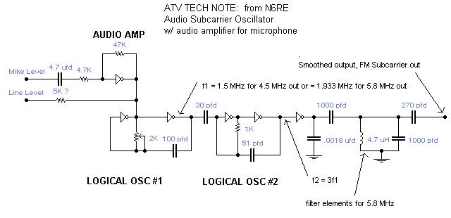
A single integrated circuit (IC) provides all amplifiers: the 74HC04 Hex Inverter, which is a digital component. The second oscillator synchronizes to three times the frequency of the first oscillator, thereby tripling the frequency modulation (FM) deviation. Utilizing the...

This car audio amplifier circuit is based on the LA47536 audio amplifier integrated circuit designed by Sanyo. This audio amplifier circuit is specifically designed for car audio power amplifiers. The LA47536 car audio amplifier IC features four output channels...
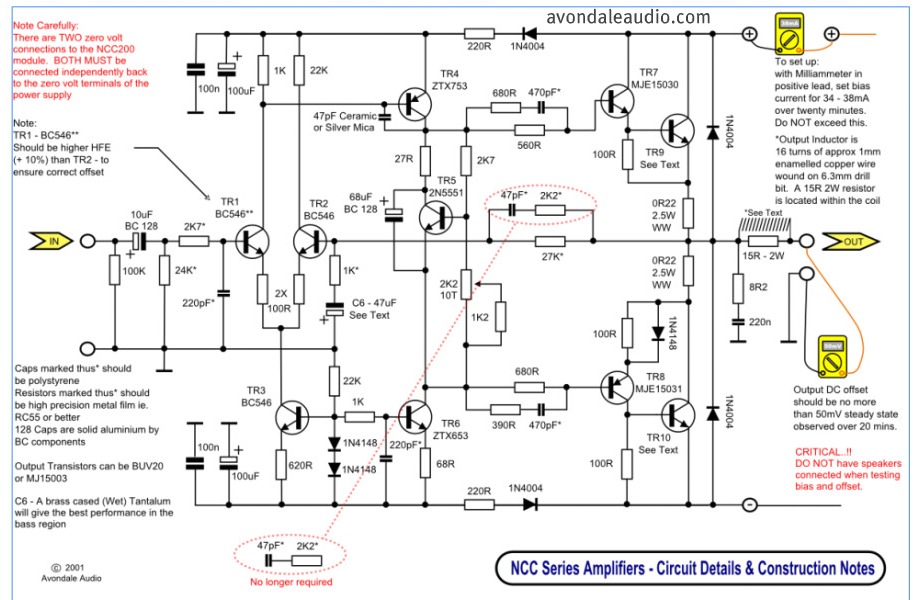
This is a simple circuit that features high-performance power amplifiers. The power amplifier is available as a PCB, along with a complete list of components. The described circuit utilizes high-performance power amplifiers, which are essential for applications requiring significant signal...

This circuit is simple and inexpensive, which is its primary advantage. Although the output power is not high, the audio quality is good due to the TDA1910's low noise characteristics. This circuit is suitable for use as a student...
This circuit is designed for an audio amplifier project to control the speaker output relay. Its primary function is to activate the relay that connects the speaker output to the amplifier after a delay of approximately 5 seconds following...