
Telephone Headgear

The design of a compact and cost-effective telephone headset can be achieved using a minimal number of components, specifically two transistors along with additional electronic parts. The primary function of the headset is to facilitate clear audio communication, which is essential in various applications, including telephony and audio monitoring.
The schematic typically includes two key transistors configured as an amplifier circuit. These transistors serve to boost the audio signals received from the microphone and ensure that the output to the speaker is at a sufficient level for clear sound reproduction. The choice of transistors should consider parameters such as gain, frequency response, and power handling capabilities to ensure optimal performance.
Additional components may include resistors and capacitors that are used to set the biasing conditions for the transistors, filter unwanted noise, and stabilize the circuit. A power supply circuit, possibly using a small battery or a USB power source, will be necessary to provide the required voltage for the operation of the transistors.
The microphone, which can be an electret type for its sensitivity and compact size, is connected to the input of the amplifier circuit. The output from the transistors is then routed to the speaker, which converts the amplified electrical signals back into audible sound.
Overall, the design emphasizes simplicity and efficiency, making it suitable for various applications where a reliable and economical headset solution is required. Proper layout considerations and component selection will further enhance the performance and durability of the headset.Telephone Headgear. Acompact, inexpensive and low component count telecom head- set can be constructed using two readily available transistors and a few other electronic. 🔗 External reference
Related Circuits
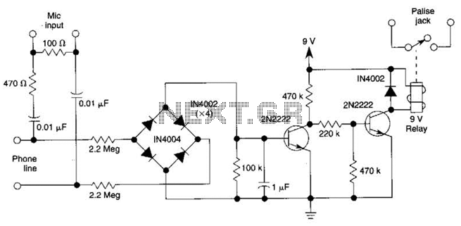
The DC voltage on a telephone line typically ranges from 45 to 50 V when on-hook and drops to around 6 V when off-hook. This circuit utilizes the voltage drop to activate a relay, which in turn controls a...
In order to achieve a status between two levels of switching for two calls at the same time, you must first establish privacy on each call. Otherwise, you will end up with all four phones talking to each other,...

This circuit is a simple telephone ringtone generator designed using minimal components. It produces a simulated telephone ringing tone and operates on a DC voltage ranging from 4.5V to 12V. This circuit can be utilized in standard intercom systems...
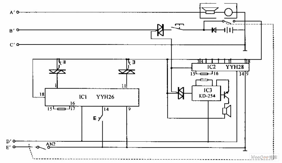
The internal telephone circuit is depicted below. By making minor enhancements to a toy telephone, it can be transformed into a functional internal telephone. This device comprises several components, including the phone unit, a decoding circuit, a ringing circuit,...
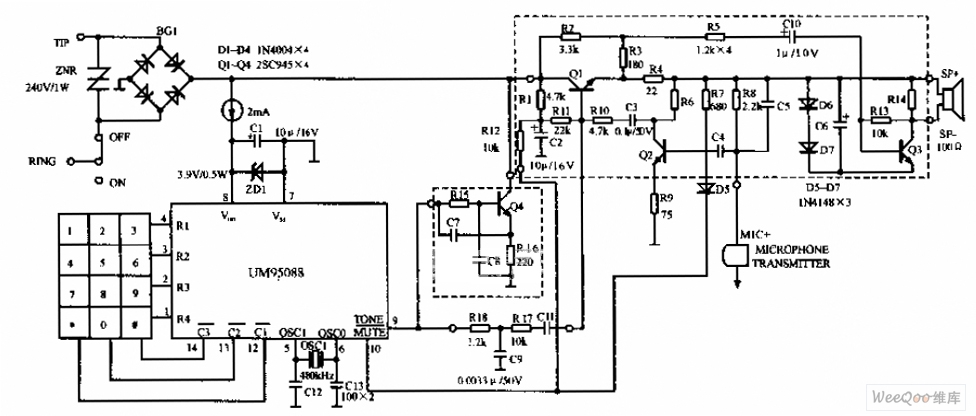
The UM95088 telephone circuit diagram is depicted in the image above. The UM95088 is a specialized integrated module designed for dual-tone multi-frequency (DTMF) telephone dialing. It utilizes CMOS technology and comes in a 14-pin dual-in-line package. The schematic for...
A telephone ringer capable of making any mains-powered device operate from the ringer of a fixed line telephone. This device allows the control of a high-powered siren or horn to amplify the low-level sound of a telephone, making it...