
Telephone Call Recording Circuit Circuit

The described circuit operates by leveraging the characteristics of the telephone line's DC voltage. When the telephone is in the on-hook state, the voltage remains high, typically between 45 and 50 volts. In this condition, the relay remains deactivated, preventing any current flow to the cassette tape recorder. However, when the telephone goes off-hook, the voltage significantly drops to approximately 6 volts. This voltage drop is the critical factor that triggers the relay to activate.
The relay serves as an intermediary switch that allows the low-voltage signal to control the operation of the cassette tape recorder. Upon activation, the relay closes its contacts, allowing power to flow to the cassette tape recorder, thus enabling it to start recording or playback audio as required.
Additionally, the circuit incorporates an audio extraction network designed to capture the audio signals from the telephone line. This network typically consists of passive components such as resistors and capacitors, which filter and condition the audio signal before routing it to the microphone input of the cassette tape recorder. The audio quality and clarity are maintained through careful selection of these components, ensuring that the recorded audio accurately represents the original sound captured from the telephone line.
Overall, this circuit effectively combines telecommunication and audio recording technologies, providing a practical solution for capturing audio directly from telephone conversations. The dc voltage present on a telephone line is usually around 45 to 50 V on-hook and 6 V off-hook. This circuit uses This drop in voltage to activate a relay. The relay controls a cassette tapeTecorder. Audio is taken off through a network to the microphone input of the cassette.
Related Circuits
This room light controller project automatically uses a microcontroller to manage a visitor counter, providing a reliable circuit for controlling the room lighting. The room light controller circuit integrates a microcontroller that processes inputs from a visitor counter. This setup...

The adjustable voltage monitor can be used to check whether the voltage in a circuit remains within a given range. If the DC voltage is less than the voltage at pin 5 of U1-B, then LED1 will light. If...
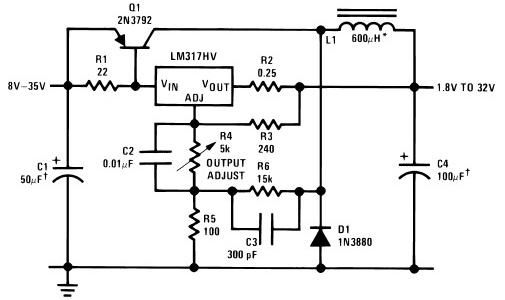
The circuit diagram of this LM317 power supply electronic project requires a few external components. The input voltage for this project must be between 8 and 35 volts, providing a variable output voltage ranging from 1.8 volts to 32...

The figure illustrates a current boosting circuit configuration utilizing the PGA202 and OPA633 operational amplifiers. This circuit enhances the output current capability of the PGA202 operational amplifier, leveraging the performance characteristics of the OPA633 to achieve a higher output...

A bipolar stepper motor drive circuit is presented, utilizing eight transistors to operate two phases. This bipolar drive circuit can accommodate both four-wire and six-wire stepper motors; however, it is primarily designed for four-wire bipolar configurations, which can significantly...

This circuit prevents surges caused by power failures or interruptions, protecting electrical appliances from damage. It automatically switches to a short circuit mode when necessary. The surge protection circuit is designed to safeguard sensitive electronic devices from voltage spikes that...